I see there are different types of Adaptive current mode controllers.Adaptive current mode controller
I often use peak current mode. In papers from schools then measure the inductor current but I always use the switch current because it is easy to get at.
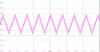
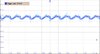
I used, decades ago, a PWM that used the ripple voltage on the output capacitor to measure inductor current. Current in the L is very related to current in the C. The loop response is good when looking at ripple voltage on the output C.
In boost supplies I usually use current mode (not adaptive). Measuring current at the switch. I have used "constant off time" or "constant on time" in current mode with very good results. I think they are very close to what you are doing.
I almost never look at current in the L directly because it takes too many parts to see it. I look at current in the switch. There was project where I looked at the current in the diode.
Link for you