Continue to Site

Welcome to our site!

Electro Tech is an online community (with over 170,000 members) who enjoy talking about and building electronic circuits, projects and gadgets. To participate you need to register. Registration is free. Click here to register now.

  • Welcome to our site! Electro Tech is an online community (with over 170,000 members) who enjoy talking about and building electronic circuits, projects and gadgets. To participate you need to register. Registration is free. Click here to register now.

Op Amp for Current Sensing

Status
Not open for further replies.

xpassionzxc

New Member
Hello,

I'm currently trying to test the current of my dc-dc boost converter across a 0.1 ohms resistor.

I've tried an op-amp called uA741 Operational Amplifier. However, I felt that it is too slow and its quite noisy at the output.

In terms of slow, the waveform has a phase shift at the output of the op amp as compared to the current probe.


May I ask if anyone has a better Operational Amplifier that they can recommend to measure the current across a circuit?

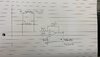
Circuit of my boost converter.

1603461812619.png


The 0.1 ohms resistor is placed before L2. So the op amp will measure the value(voltage) across the resistor using the differential configuration of an op amp.
My MOSFET runs at 30Khz.

-Supply Voltage for Op amp can range from +-15V.
-Gain of 10 at the output to reproduce the current measurement. (Since 0.1ohms resistor is being used)


Thank you
 
Last edited:
Please post your circuit. How many volts (mV) across the 0.1 ohm resistor? (what current)?
What supply voltage for op-amp? (+12V) or (-5 & +5) ?
What frequency? "too slow"
How much gain do you need?
 
The 741 has a gain bandwidth of 1mhz. Which is to say; at a gain of 10 it is only good for 100khz. So at 30khz you only see to 100khz, with phase shift. Pick a amp with a gain bandwidth of 10mhz to 50mhz.
What is the voltage at Vg, C1, C2? The amp needs to see the voltage at C1.
 
The 741 has a gain bandwidth of 1mhz. Which is to say; at a gain of 10 it is only good for 100khz. So at 30khz you only see to 100khz, with phase shift. Pick a amp with a gain bandwidth of 10mhz to 50mhz.
What is the voltage at Vg, C1, C2? The amp needs to see the voltage at C1.

My Vg is 15V. For C1 and C2, I need to measure it at the classroom haha.

Anyway, At the duty cycle of 50%, I'm able to get 64V.
 
At the duty cycle of 50%, I'm able to get 64V.
Vg=15 50% C1=30V 50% C2=60V Sounds right to me.
-----------edited----------
You are looking at 0.1V on top of 30V. So you need good 1% resistors.
The 30V might be above the supply voltage of the op-amp so: Add C3,4 to strip off the 30V.
C3=C4!
1603463209493.png
 
Vg=15 50% C1=30V 50% C2=60V Sounds right to me.
-----------edited----------
You are looking at 0.1V on top of 30V. So you need good 1% resistors.
The 30V might be above the supply voltage of the op-amp so: Add C3,4 to strip off the 30V.
C3=C4!
View attachment 127621
How much of rating do you recommend for the C3 and C4?
Also, do you have any recommendation for the Op-Amp chip because in the market there is just too many haha.
Lastly, thanks a lot for the suggestion.
 
Keep the resistors close to op-amp.
low frequency response = 1/2*3.14*R*C Size C for 3khz or 300hz of something well below your 30khz.
Choose a amp that is 10x faster than the 741. Do you know how?
 
Low Frequency Response = 1/2 * 3.14 * R * C

So I select my the low-frequency response myself and calculate the value for C? How about R? Where do I get the value of R .


Not really!
 
I get parts from digikey.com but almost all places have good search engines.
I went to digikey.com and typed "opamp" into the window. Then I choose "linear amps ....." where they say there are 24000 choices.
link1
Then I choose 1 amp/IC, and bandwidth of 10 through 50mhz.
link2 now there are only 1200 choices. lol
Push the "in stock" box. That will help a little. Maybe you want through hole package only. Or only 8 pin.
 
1k for the input resistors and 10k for the feedback resistors. 1k, 1k, 10k, 10k
Noted! Thankyou.


Can I ask another question?

Why do I get this? Shouldn't I be getting the same value? Op Amp 741

The resistor is connected to the same dc-dc boost converter circuit as we were talking about.

I'm thinking practical op-amp is not ideal as compared to theory? That's why there is a gain of 10~ even using a unity gain amplifier configuration.
 

Attachments

  • WhatsApp Image 2020-10-23 at 10.56.31 PM.jpeg
    WhatsApp Image 2020-10-23 at 10.56.31 PM.jpeg
    82.9 KB · Views: 145
Last edited:
Opamps have "input common mode voltage range" in the data sheet. That is the voltage where the amps works. The ua741 should have the input voltage about 3 volts away from the supply voltage. So a supply of 15V and 0V will work with input voltage of 3V to 12V. That is why if is common to have a negative supply to work with voltages near ground.
 
Measure the current at RS and you can almost see the current at RL. It might be easy to see RS. It is at ground so not 30V to get rid of.
1603466399458.png
 
Status
Not open for further replies.

Latest threads

New Articles From Microcontroller Tips

Back
Top