Continue to Site

Welcome to our site!

Electro Tech is an online community (with over 170,000 members) who enjoy talking about and building electronic circuits, projects and gadgets. To participate you need to register. Registration is free. Click here to register now.

  • Welcome to our site! Electro Tech is an online community (with over 170,000 members) who enjoy talking about and building electronic circuits, projects and gadgets. To participate you need to register. Registration is free. Click here to register now.

Op amp audio filter questions

Status
Not open for further replies.

mojozoom

Member
I'd like to build a set of all-pass filters to change the shape of the subwoofer phase curve in my car audio application in order to get it to align more closely with the midrange drivers. Based on testing and modeling of the all-pass filters in REW, I've come up with three all-pass filters to apply:
1) fc=30 Hz, Q=6
2) fc=63 Hz, Q=3.6
3) fc=95 Hz, Q=2.3

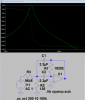
Doug Self's filter book advises to avoid the two single op amp all-pass filters for various reasons, so that really leaves the two op amp MFBP and Fliege circuits. The MFBP all-pass filter is a 1-2BP arrangement with an inverting BP section followed by a summing amplifier that multiplies the BP output by 2 and sums it with the input. It takes two op amps, one for the BP and one for the summing.

**broken link removed**

My first question for you guys is this:
If I use the MFBP configuration for these three filter sections, is there any way to combine them such that they all use the same summing amplifier stage?

Doug's book indicates that most of the noise in the MFBP filter design comes from the summing stage, so if I could eliminate 2 of the 3 it would probably perform better.

Next question:
Does it really matter which order I arrange the filters in the circuit?

Thanks!
 
Yes, you can use one summing stage for all the filters.
Just add more input resistors to the summing junction.

Don't know what you mean by the order of the filters. :confused:
As I understand your circuit, they are all in parallel to the summing amp.
 
The "order" of a filter is the number of RC sections in it. A third order filter has 3 RC sections and positive feedback to make the passband flat but the cutoff sharp.
A bandpass filter is not used for an audio active crossover. Instead there is a Butterworth or Linkwitz-Riley lowpass filter then a matching highpass filter. When the filters match then there are no phase problems.

For a midrange filter use the highpass filter first then the lowpass filter second so it cuts hiss.
 
Zapper,

I split them up and applied the same 5k to each, but that made a real mess out of the final output. I feel like there has to be some inverse addition in this problem in order to make the 3 BP filters and 1 full range sum up the same way as 1-2BP does for the all-pass. Here's the circuit as I have it now:

**broken link removed**

Any ideas on how to fix the summing? The output of each stage looks exactly like you'd expect, with a 180 degree phase shifts taking place at various frequencies.

Thanks!
 
Likely, you need to taylor R4, R3, R20, and R19 to get the relative amount of each...

Post your .asc file, and I will play with it...
 
Hopefull my .asc file uploaded and is attached to this post somehow. If not I suppose I can just post the text and you could cut and paste.

Thanks for the help!
 

Attachments

  • sub second order all pass MFBP3.asc
    4.7 KB · Views: 133
Is this closer to what you were trying to do? You were missing an inverter.

MFBP.png


I didn't have your opamp, and the supplies looked too high??? I uploaded a modified .asc
 

Attachments

  • MFBP3.asc
    5.7 KB · Views: 143
Why are you making a foghorn sound with those narrow bandwidth filters? I simulated the first one:
 

Attachments

  • bandpass filter.png
    bandpass filter.png
    20.6 KB · Views: 146
Well it's better looking than what I was getting with that circuit, but not matching the original version of teh circuit. When I used the 3 completely separate MFBP sections (2 op amps each) it produces basically flat amplitude across the audio spectrum (hence the all-pass moniker) and the funky phase shift that I'm trying to achieve, like this:

**broken link removed**
 
Why are you making a foghorn sound with those narrow bandwidth filters? I simulated the first one:

It's really not supposed to make any sound, but to all-pass the amplitude without effecting it. The goal is to alter the phase profile of the subwoofer to compensate for the phase shift of the low-pass filter and to parallel the phase profile with that of the midbass drivers. Once they're parallel I can use digital delay via the DSP to move the entire curves around to sync them up.

The end goal is to keep the phase difference between all the drivers within 90 degrees of each other (much closer if possible).
 
Here's the LTspice file for the original version before we starting trying to minimize op amp count. This one demonstrates how it's supposed to work.
 

Attachments

  • sub second order all pass MFBP1.asc
    5.7 KB · Views: 142
Hi,

There will be and should be a big difference between the connections where all are in series and all are in parallel. The short answer is that in the parallel connection all the gains are added and that even includes those filters sections that are inactive, while in the series connection the gains are multiplied so any sections with gain 1 just pass along the signal to the next stage. We can look at this in more detail.

First, a single filter will pass signals with different gains at different frequencies, and we look at least at two different gains. The first gain would be the pass band gain, and the second would be the stop band gain. We can call these Gp and Gs respectively. This means for three filters we have three sets of gains to consider as a minimum:
Gp1, Gs1, and Gp2, Gs2, and Gp3, Gs3. The numbers 1 to 3 indicate which of the three we are talking about.

The total gain G can now be computed by knowing that only one filter is operating in it's pass band at a time. It does not matter if they overlap right now because we only look at the two frequencies for each, at least for now. For a single tone test frequency this gives total series gain GS and total parallel gain GP as:
GS=Gs1*Gs2*Gs3
GP=Gs1+Gs2+Gs3

We can see there is a world of difference already because in one config the gains are multiplied, and in the other config they are added. We have one more gain to consider, and that is the full response gain which we can call G4, and that gets added to the others in BOTH configs:
GS=Gs1*Gs2*Gs3+G4
GP=Gs1+Gs2+Gs3+G4

So you see we have a problem. The stop band gains in the first config above would have to be all 1 (one), while in the second config the stop band gains would have to be all 0 (zero). These numbers refer to the gain Vout/Vin and not the gain in db.

For example, if we had all stop band gains equal to 1 instead of 0 and we had one filter in the pass band with gain of 2, and G4=1/2, the two configs would yield:
GS=1*1*2+0.5=2.5
GP=1+1+2+0.5=4.5

You can see there is an almost 2:1 difference in total gain at that one frequency, and we only have to show that is does not work for one frequency to prove that it wont work for a given single frequency. It's also true that if we make all the stop band gains zero then the two gains still come out different. To be sure we'd have to look at two test frequencies, but you can see where this is going.

The conclusion then is what works for one config does not work for the other.
If you are getting the RIGHT response from the series connections, then you have to keep it that way without altering every filter. There is also a chance that the filters can not be easily altered in a way that would allow the other config.

Lucky these circuits are not that hard to analyze analytically either so we could work up a total analytical solution if need be. If the simulations work for you then that's good too and saves some work.
 
Last edited:
What is wrong with the positioning of your speakers that requires such a HUGE phase shift? Wouldn't the speaker that is far away also be delayed?
 
Everything is wrong with the positioning of the speakers - it's a car. I don't have the option / desire to move them from the stock positions. The sub is the furthest away and gets very little delay. The left side speaker is closest and that guy gets the most delay from DSP to line it up with the other driver.

The sub is using a 36 db/octave low pass at 70 Hz, and that's what's generating most of the phase shift. It's pretty flat until it gets to the filter frequency, then starts a steep slope.

But I think I understand why I can't get away with fewer op amps - thank you MrAl! I've been Fritzing breadboard layout for both the MFBP and the Fliege and even though the Fliege has one less resistor it's a pain to lay out. I'll probably go with the MFBP for that reason. That's 2 op amps per filter, 3 filters , so 6 op amps.

Do I need to add an input buffer op amp as well? If so that's 7, and a pair of quads. If it's only 6 I need then maybe a quad and a dual?

Thanks!
 
36dB per octave lowpass filter?? But 18dB per octave is plenty.
My car audio systems sound fine without your maze of narrow filters and extreme phase shift.
 
I've been building and tuning car audio for 35 years. I used that slope on the sub for a reason, but that's not what this post or forum is about. Please stop trying to shift the focus of this thread, as I'm try to learn about op amps, not teach about car audio.

Thanks for your opinions, but why I am doing this is irrelevant. The technical aspects of how to apply op amps are the focus of the discussion.

Hi,

Did you read post #12? I was explaining what the differences are with the series vs the parallel connections of the op amps are. If the gain works in one config it wont work in the other, so that's a very important aspect of this. It's all about how the stages add up to the total gain.
You did not comment on that post so i dont know if you got anything out of it or not.

I did - thanks again for spending the time to explain it in so much detail. Just for fun I tried to arrange the three BP sections in series, then sum that signal with the input. It actually came out pretty close, but as you said the gains of each BP stage play a huge part in it, and the amplitude never quite came out flat for me. It always had about +/- 5 dB of ripple near the filter frequencies. Overall it seems too dicey to mess with when the two op amp filter configs works so well.

I did figure out clean a breadboard layout for the Fliege version of the filters, and since it has a much lower spread between resistors I'm planning on using it instead of the MFBP anyway. If I include a buffer in the circuit then there's 7 total op amps, so two quads fits the bill nicely.

**broken link removed**
Here's the breadboard of the buffer and first all-pass filter:

**broken link removed**


And please note that my last post wasn't directed at you at all - I really appreciate your help and your time.
 
In reading through the op amp datasheets, I came up with another question. Many of these include graphs of phase versus frequency, and it's apparent that some of them have pretty severe phase shifts going on below 100 hz. For a circuit that's targeted at subwoofer frequencies (10-200 hz) and specifically intended to modify phase response, I'm thinking the phase shift in that region might be one of the criteria used to select an op amp. Or is this information not as applicable as I think, maybe due to the test method?

The TL074 is particularily nasty below 100 hz:
**broken link removed**


**broken link removed**

**broken link removed**


And some don't even show the phase response below 10k:
**broken link removed**
 
The phase shift is shown without any negative feedback and the voltage gain of the opamp is almost 1 million. Adding negative feedback to reduce the gain, reduce the distortion and flatten the frequency response also flattens the phase shift for it to be close to zero.
 
Status
Not open for further replies.

Latest threads

New Articles From Microcontroller Tips

Back
Top