Continue to Site

Welcome to our site!

Electro Tech is an online community (with over 170,000 members) who enjoy talking about and building electronic circuits, projects and gadgets. To participate you need to register. Registration is free. Click here to register now.

  • Welcome to our site! Electro Tech is an online community (with over 170,000 members) who enjoy talking about and building electronic circuits, projects and gadgets. To participate you need to register. Registration is free. Click here to register now.

Op-Amp appears to be stable when operating below the minimum gain specified on the datasheet?

Status
Not open for further replies.

stryker12

New Member
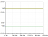
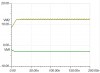
I've been testing this circuit configuration with the THS4021 op-amp, which is "stable at a gain of 10 (-9) or greater" according to its datasheet, and I can see that it's true for certain low gains. There is a lot of voltage oscillation at the output when R1 is set to a value below 200 ohms, but for R1 = 250 ohms or 300 ohms for example, the circuit seems to work fine and I get no oscillation in my output. Why is that? And does that mean I can use this exact set-up in my design or should I select a different op-amp if I am looking for a gain of -4 V/V? I've attached the waveform for reference.

118804
 

Attachments

  • waveform1.PNG
    waveform1.PNG
    7.3 KB · Views: 152
  • waveform2.PNG
    waveform2.PNG
    7.4 KB · Views: 153
It may work with a specific op amp, but the next device (even of the same type) might oscillate.
You never design outside the design specs of a device (unless you don't care if the design works reliably under all conditions).
Use an op amp that's stable down to a gain of 1.
 
Try adding a low value resistor in series with pin 6, to reduce the slew rate of the final output signal.
eg. Something like 10R or 100R.

You could also add a low value cap, 10pF - 100pF or more between output and -input, either directly or in series with another low value resistor.
 
1--"stable at a gain of 10 (-9) or greater"
2--Why R121, R31. That is not good.
3--C1? This amp is not happy driving a capacitor. " Therefore, for capacitive loads of greater than 10 pF, it is recommended that a resistor be placed in series with the output of the amplifier, as shown in Figure 33. A minimum value of 20 Ω should work well for most applications. For example, in 75-Ω transmission systems, setting the series resistor value to 75 Ω both isolates any capacitance loading and provides the proper line impedance matching at the source end."
Do you really need this fast of a amplifier?
 
Status
Not open for further replies.

Latest threads

New Articles From Microcontroller Tips

Back
Top