Continue to Site

Welcome to our site!

Electro Tech is an online community (with over 170,000 members) who enjoy talking about and building electronic circuits, projects and gadgets. To participate you need to register. Registration is free. Click here to register now.

  • Welcome to our site! Electro Tech is an online community (with over 170,000 members) who enjoy talking about and building electronic circuits, projects and gadgets. To participate you need to register. Registration is free. Click here to register now.

One speaker is picking up radio module noise

Status
Not open for further replies.

mik3ca

Member
I currently made a module to my project which isn't quite functioning correctly. It's 4 distinct parts on one board. The radio I/O, the two independent sound amplifiers out of the LM386's and the RFID card reader.

This is the circuit:

circuit.png

The actual inverter IC I used is 74HCT04 because it allowed me to convert 5V to 3V.
RAD1 is the connection to the radio module board.
J1 is a 1cm wire for easier routing

Capacitor marked 3V is 47nF but I also have a 220uF cap in parallel with it on another board that this one connects to via a 5 inch ribbon cable.

Capacitor for LM386 gain is 10uF

Output capacitors are 100uF and are attached to zobel networks consisting of 10 ohm and 4.7nF caps in series.

Variable resistors are 20K

The inputs to each amp is connected through the same 5 inch ribbon cable to the analog output of an ISD1760 IC. and right next to that output is a 10K pull-down resistor.

When I run the circuit, every time bits are transmitted through the attached radio module (HM-TRP), I get interference at the output of the LM386 closest to the module in the form of oscillations.

The other speaker however has ultra faint oscillations.

Each speaker is 0.5W 8ohm and is connected via twisted 22 AWG wire thats about 4 inches long.
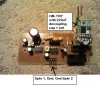
Here's the PCB:

circuit2.png


I used separate voltage lines for the LM386 because I can give it more power than the standard 5V so I hooked that to the battery via a long wire.

Now what I didn't include in my circuits which I added on after was a 1000uF capacitor between the 7.2V connection point and ground. That did stop the oscillations that previously occurred during audio playback.

So what can I do here to prevent hearing oscillations every time the radio module transmits data?

Its transmitting on 915Mhz, and data is being transmitted at 38400bps
 
The amplifiers have high gain due to the RC between pin1 and pin8 so the ribbon cable on the inputs instead of shielded audio cable picks up interference.
 
OK, so could I get away with replacing that cable in the audio line with an LC low pass filter? and if so, is it better to put that filter closer to the LM386 amplifier board or closer to the ISD1760 output? and do I set the filter to a frequency of slightly above the data baud rate? and is there any disadvantage of using a larger capacitor value and a smaller inductor value as opppsed to a smaller capacitor value and a larger inductor value?
 
An LC lowpass filter cuts away audio sounds. Is that what you want?
 
I can agree that filters cut off sounds but since my data rate is higher than the sounds we hear, wouldn't a 38Khz filter work (since I'm using 38Kbps baud)?

The only alternative I could think of off the top of my head is to make the circuit board size bigger and put all the audio sections as far away from the radio as possible.

I mean there has got to be a way to filter out the interference with capacitors. Then I wonder if a high pass filter will work because the interfering sounds are at a low frequency (under 60hz)
 
Your audio output capacitor is only 100μF feeding a tiny 0.5W 8 ohm speaker so the highpass RC already cuts 200Hz and lower frequencies and the little speaker cannot play low frequencies anyway. I don't think an additional highpass filter will stop the interference. I think the input of the high gain LM386 is overloaded by the strong nearby radio transmission and the ribbon cable on the amplifier inputs is the antenna that picks it up.

Your 4.7nF zobel capacitor is too small which might make RF interference worse. The datasheet of the LM386 shows 0.047μF that is 47nF.
 
ok ill replace the capacitors and see if that works.

And would interference be gone if I put the ribbon cable inside a ferrite rod (the long sticks thats used for AM radios)?
 
Here's my board. I changed the zobel caps to 47nF and I still have no luck. I even turned the trimmers to minimum gain.
 

Attachments

  • IMG479.jpg
    IMG479.jpg
    173.5 KB · Views: 250
I think the nearby radio transmitter output is overloading the amplifier input causing interference. The gain trimmer is not at the input, instead it adjusts the negative feedback. Shielding the ribbon cable still allows the RF to spray onto the input wiring and IC pin.
 
Ok and the 2-pin jumpers is where I plug in my speakers.

So I guess my best bet then is to run a ribbon cable of at least a few inches to separate the radio module from the rest of the board with some filters on the data lines?
 
I attempted a minor change to my circuit. Instead of having the radio module close to the board, I created a twisted-quad wire connection (basically two twisted pairs twisted together) between the multimedia board (that I already shown) and the radio module. Each wire is about 5 inches long. I even tried another HM-TRP radio module (same kind but I have many of them), and I still get the oscillation sound when the HM-TRP transmits data. Is there anything else I can try to get rid of the problem or is my only solution lowering the volume greatly?
 
All transceivers I have seen mute the audio when they transmit.
 
I've seen walkie talkies do that but I'm making a game. If I mute the audio while transmitting data then the sound coming from the audio chip could sound scratchy because of how many times the sound goes on and off plus on top of that add the microseconds to start and stop the audio in software.
 
ok so I'm in the process of looking for software that will pulse my sounds and if that's acceptable, could I somehow modify this circuit using maybe one extra IC so that when the transmitter starts (falling low edge detected on transmitter pin), the audio shuts off for the duration of one byte (about 26uS)?

If the audio was digital, I could get away with a 4538 CMOS IC but I need something that will work with audio.
 
What happens if you take the audio cable off the ribbon input and transmit? Does the interference get better? If not, what happens if you short the input to the LM386 (without the input cable)? How about putting about 100pf across gnd and the audio in pins of the LM386, first without the input cable, then with? If the noise comes back with the input cable, does putting 1k in series with the input cable and the 100pf close to the 100pf make it any better? Does lifting the ground of your input ribbon cable make it worse or better?

Shutting the audio off for 26us corresponds to about half a cycle of 38kHz. You are unlikely to hear the effect of a glitch of such a short duration. Your TX RF is probably being rectified by something in the LM386 making a DC shift, which is taking time to settle, or you're getting a dip in the power supply of the system feeding your 386 (which seems to have its own PSU). Even if your were a bat the sort of speakers you would connect to this won't pass such high frequencies.
 
Last edited:
What happens if you take the audio cable off the ribbon input and transmit?
The audio line and the data cable are different

How about putting about 100pf across gnd and the audio in pins of the LM386, first without the input cable, then with?
After reading literature, I decided to redo my PCB so that the audio output is more at the top left (farther away from the transmitter by at least one inch) and I made the ground plane bigger. I'll try a 10K resistor connected direct from input to ground and if that fails then I'll look into a small pf capacitor
 
Ok so I did more experimenting and noticed no change in interference when I hooked a 100pF ceramic cap to either audio input and ground but I did notice the interference went a bit fuzzled when I hooked a 100pF cap between adjacent pins of the radio module itself. Perhaps I should add more capacitors and resistors or even ferrites to the radio module?
 
One thing that seems to work which is not what I want to do in my design is to have the radio module 6 inches away from the board via twisted wires but the module must point in the opposite direction. I wonder if I could get things working by wrapping the entire radio module (minus antenna) first in electrical tape then in aluminum foil.
 
Status
Not open for further replies.

Latest threads

New Articles From Microcontroller Tips

Back
Top