Continue to Site

Welcome to our site!

Electro Tech is an online community (with over 170,000 members) who enjoy talking about and building electronic circuits, projects and gadgets. To participate you need to register. Registration is free. Click here to register now.

  • Welcome to our site! Electro Tech is an online community (with over 170,000 members) who enjoy talking about and building electronic circuits, projects and gadgets. To participate you need to register. Registration is free. Click here to register now.

One circuit at a time switch

Status
Not open for further replies.

mrg1999

New Member
I'm trying to create a toy for my young nephews that will generate different sound effects with the press of different push button switches.
My problem is if they press another push button while the first sound effects IC is still playing, both sounds will be playing simultaneously through the speaker (common speaker for all sound effect IC's).
There are six different IC's and six different push button switches.

I can design a nightmare circuit with relays or transistors that will only allow one switch to operate at a time but there has to be a better way.

Optimally, if one switch is pressed the IC will play it's sound but if another switch is pressed while the first is still playing it's sound, the first IC will be turned off and the second turned on (additionally, if a third button is pressed, only that IC will receive the supply voltage and all others will be off).

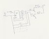
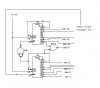
I'm hoping someone has more experience with an integrated circuit switch that would allow only one device to be active at a time. I've uploaded a block diagram.

Thank you in advance!
 

Attachments

  • Block Diag.pdf
    28.3 KB · Views: 332
I'm thinking you need double pole switches with the power bus going through one pole of all the switches. The power bus switches would be normally closed, pushing any switch will reset power.

I'm sure the switching of the ICs could be done with the other poles with some sort of time delay action or logic/inverters.
 
Yes it would be nice to know if these things have a reset pin or if removing power is the reset option.

I've never really thought much about this kind of circuit, but I have seen a kind of "disable all" done with a switch.

What I'm seeing in my head is to remove power from all the IC's by having Vss power run through one pole of every double pole switch, which would all be normally closed.

Now, when the desired switch is pressed, it would remove power to all the ICs because it would be an open series circuit. But these switches would have to be momentary, because power would have to be reapplied almost instantly. A learning question for me, is there such a thing as a "momentary pass-through" switch, where a push of the switch would only momentarily break the contact, then reconnect even while pushed? Kind of like a spring that "reloads"? It seems I've seen this before but don't know what its called.

Then, the other pole of the switch, the one connected to the trigger pin of the IC of choice, would also be momentary contact, but it would only engage when fully depressed. This way there is a time delay between the momentary break/reapplication of power to all the ICs, and the trigger voltage going to the IC.

This would be how I would do it if I could identify the proper switch! :eek:
 
Thank you for all the responses.

Unfortunately, none of the sound generator IC's have resets...I've attached a sample circuit.

I also uploaded a circuit idea using a 74HC4051N 8 channel anolog switch.
The data sheet is here: https://www.electro-tech-online.com/custompdfs/2009/11/74HC_HCT4051_3.pdf

The press of the momentary PB switch will connect the trigger of a 555 timer to ground thru the 8 channel switch. When the 555 output goes high, part of the output is sent to the "enable" terminal of the 8 channel switch which causes all of the switch circuits of the 74HC4051 to be forced open.

The output of the 555 will also be used to power up the sound generator IC.
The 555 will be set up as a one-shot and it's duration will be long enough for the sound IC to play it's particular sound effect.

All the other PB switches will be disabled during this time...at least that's the theory!

IC1 thru IC3 are the sound effects generators, SW1 thru SW3 are the momentary pushbutton swithces.

Any comments or advice are greatly appreciated.

Thanks again.
 

Attachments

  • sg3.pdf
    49 KB · Views: 221
  • Diag2.pdf
    19.4 KB · Views: 213
use transistor switches for each ICs, 4017 can be used in such a way to function as you wish ie: will roll and latch at the last switch pressed,to turn on the particular switching transistor. i have long before done such a design using it, shortly i may post it for you.
 
I was thinking of the 4017 as well but

the sounds would be in same order each time regardless of pressed button

My thought was using D flip flpos then using the pushbutton to clock the D flip flops but the data inputs are connected to the push button as well.
pressing button 4 would input a data HIGH but all the other IC outputs would be disabled.
think of a data selector like a 74157, 74153 , 74152 or even a 74150
could also be done with simple nand gates (might be easier)
just control which IC output goes to the speaker.
 
4017 will do it

yes you are correct it will follow the same order, but what if you use a high frequency clock? you will not feel the suden change, see the diagram i have attached, hope it would work as a latching switch only one at a time, i have built it and used it long before for a slector switch application. just try
 

Attachments

  • selector.jpg
    selector.jpg
    63.4 KB · Views: 383
mbarazeen

Thanks for that circuit, I think that may do the trick.
I'm going to trigger a 555 from the selected output of the 4017 which will power up the associated sound IC and hold the enable of the 4017 high until the sound IC is finished playing, that way if another switch is pushed while the selected sound IC is playing it will have no effect.

Now, if I want to use more than ten pushbuttons and sound IC's is there a way I can cascade two 4017's ?

Thanks for the help.
 
One other thing,
I'm assuming output #7 is tied to the reset to limit the count to 6 switches.
If I want to use all ten outputs then I would leave the reset pin low, correct?
 
correct, just see the attached diagram how you can connect more then one 4017, you can make any number cascaded.
 

Attachments

  • circuit.jpg
    circuit.jpg
    23.2 KB · Views: 534
Status
Not open for further replies.

Latest threads

New Articles From Microcontroller Tips

Back
Top