Continue to Site

Welcome to our site!

Electro Tech is an online community (with over 170,000 members) who enjoy talking about and building electronic circuits, projects and gadgets. To participate you need to register. Registration is free. Click here to register now.

  • Welcome to our site! Electro Tech is an online community (with over 170,000 members) who enjoy talking about and building electronic circuits, projects and gadgets. To participate you need to register. Registration is free. Click here to register now.

Old Farnell bench power supply improvement.

Status
Not open for further replies.

diy didi

Member
Hi Guys and Gals.
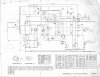
I have an old Farnell bench supply that is working fine, but I would like to improve the internal voltage reference. It uses a transistor/ zener CC source to drive a 5.6V zener.
I have attached the diagram. The part of the circuit I'm referring to is in the top-right side.
Is there an improved arrangement I can build in here without totally going too haywire??
Any input will be appreciated. Thank you!!
 

Attachments

  • OrigRegPwrSupply-cct.jpg
    OrigRegPwrSupply-cct.jpg
    833.9 KB · Views: 159
I have an old Farnell bench supply that is working fine
I guess that says it all.

What do you want to improve, and why?
Does it not meet your current* requirements?

If it works correctly, leave it alone and be happy using it.
Otherwise rip out all the insides except the transformer and the meter and start again with a completely new design using modern components.


*Sorry, a bit of a pun there, I couldn't resist it!

JimB
 
I suppose, seeing as he mentioned the 5.6V zener reference, he could replace that with a TL431 precision voltage reference, and a preset to adjust it to 5.6V.

However, the 5.6V zener is already fairly reasonable, as it's chosen for it's close to zero temperature coefficient.
 
The 3.3 volts zener sets the current (Together with R20) through the 5.6 volt zener. The 5.6 volt zener is the actual voltage reference. How far out is the voltage across the 3.3 volt zener ?

Les.
 
As Les said, it's the 5.6V zener that sets the current, the 3.3V one is part of the constant current source for the 5.6V zener.

What voltage do you get across the 5.6V zener?.
 
The 3.3 volts zener sets the current (Together with R20) through the 5.6 volt zener. The 5.6 volt zener is the actual voltage reference. How far out is the voltage across the 3.3 volt zener ?

Les.
I measured 2,8v across the 3,3V zener.
 
I even thought if replacing the 3,3V zener with an LED. Rework the resistor values to get the same current as in the schematic?
Some people say a green led is best?
Don’t know why that would be.
 
I even thought if replacing the 3,3V zener with an LED. Rework the resistor values to get the same current as in the schematic?
Some people say a green led is best?
Don’t know why that would be.

Probably because it's closer to 3.3V, however, why would you imagine an LED is better than an actual zener?.

2.8V across the 3,3V zener is probably quite normal, the actual voltage depends on the current through it, and on the tolerance of the zener.

If it's 2.8V then the circuit will still work perfectly, just that the constant current will be a little lower (which will make no difference, it's been 'constant' is what matters).
 
With a supply of that type, you're always setting the output voltage with reference to a meter, so the absolute accuracy of the voltage reference isn't that important. I always set mine with an external digital meter if I care about an accurate voltage.
However, I suppose, the two things that could be concerning you might be:
1. Drift as the instrument heats up
2. Load regulation
As suggested in #4 you could probably use a TL431 as a replacement for the Zener for better stability, but as for better regulation... that would require increasing the feedback loop gain. I'm not expert enough to make any suggestions about that, but I suspect it would mean a major re-design.
Put another way, Farnell's engineers probably made it as good as they could with those components, and you might find you need to do a very substantial re-build to get a worthwhile improvement.

I stand to be corrected, however.
 
For what its worth. I noticed that if i decrease the 2k7 in series with 3v3 zener to 1k2, the voltage across the 3v3 zener comes up to 3,3v. Does this mean it is not getting enough current?
 
Last edited:
For what its worth. I noticed that if i decrease the 2k7 in series with 3v3 zener to 1k2, the voltage across the 3v3 zener comes up to 3,3v. Does this mean it is not getting enough current?
Low voltage zener diodes do not have a well defined zener voltage.
The zener voltage varies over quite a large range as the current through the zener diode is varied.
It is most likely that this is the effect which you are seeing.

JimB
 
For what its worth. I noticed that if i decrease the 2k7 in series with 3v3 zener to 1k2, the voltage across the 3v3 zener comes up to 3,3v. Does this mean it is not getting enough current?

It means it's not getting enough to give 3.3V across the zener, but as I've already explained it doesn't matter - I'm quite bemused you randomly measured the voltage across the zener in the first place?. The existing resistor is probably calculated to give the desired current from the CCS, so randomly altering it probably isn't a good idea, when you have no idea of the design specifications from when it was designed. Just because it's a 3.3V zener doesn't mean it should have 3.3V across it.

As I mentioned previously, what is the voltage across the 5.6V zener, that's the only one that matters.
 
Thank you all for your input. I have checked the voltage across the 5V6 zener it is spot on. Even with the lower measured voltage on the 3v3 zener.
Guess I didn’t understand the circuit.
 
Status
Not open for further replies.

Latest threads

New Articles From Microcontroller Tips

Back
Top