Continue to Site

Welcome to our site!

Electro Tech is an online community (with over 170,000 members) who enjoy talking about and building electronic circuits, projects and gadgets. To participate you need to register. Registration is free. Click here to register now.

  • Welcome to our site! Electro Tech is an online community (with over 170,000 members) who enjoy talking about and building electronic circuits, projects and gadgets. To participate you need to register. Registration is free. Click here to register now.

Old Distortion Analyzer and Audio Analzyer

Status
Not open for further replies.
walters said:
"Push-pull transistors alternate during the waveform. One transistor conducts current when the waveform goes upward, then the other transistor conducts current when the waveform goes downward. "


Using a Single Transistor in normal mode "conducts" current upward and downward whats the difference between Pull-pull VS normal mode?

Because they both "conduct" upward and downard waveforms
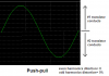
A single transistor is non-linear therefore amplifies the top of the waveform a different amount from the bottom of the waveform.
Push-pull transistors amplify their half of the waveform the same amount.

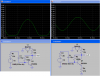
This is a copy-and-pasted sim of push-pull transistors. Each transistor compresses its half of the waveform a little but by the same amount:
 

Attachments

  • sim_push-pull.png
    sim_push-pull.png
    9.8 KB · Views: 566
This is a sim of one transistor incorrectly biased so that it clips the waveform's bottom. The other pic shows its output when it is correctly biased and with a little amount of negative feedback to make it even better:
 

Attachments

  • sim-mic_preamp_101.png
    sim-mic_preamp_101.png
    37 KB · Views: 563
Thanks alot of the pictures and help

So the "one" transistor has different compression than the push pull mode?

The "one" transistor baised correctly still "conducts" both ways and looks the same as the Push pull mode whats the difference?

From looking at the oscilloscope pictures how can u tell the even and odd harmonic percentages?

If the waveform is clipped on the lower or upper then u say the even harmonics is 40%

In the oscilloscope sim picks where is the 2nd harmonic distortion?
i still can't see it or know where its at
 
walters said:
Thanks alot of the pictures and help

So the "one" transistor has different compression than the push pull mode?

The "one" transistor baised correctly still "conducts" both ways and looks the same as the Push pull mode whats the difference?

From looking at the oscilloscope pictures how can u tell the even and odd harmonic percentages?

If the waveform is clipped on the lower or upper then u say the even harmonics is 40%

In the oscilloscope sim picks where is the 2nd harmonic distortion?
i still can't see it or know where its at

Not really, the single transistor just is DC-offset since it has no means to go negative it must sit on an offset to produce a sinewave, AC-couple will remove the offset tho
 
walters said:
So the "one" transistor has different compression than the push pull mode?
Yes. The single transistor compresses the top of the waveform when it is nearly cutoff. Each transistor of a push-pull type compresses the waveform when it conducts the most.

The "one" transistor biased correctly still "conducts" both ways and looks the same as the Push pull mode whats the difference?
I can see compression of the top half of the single transistor's waveform. It isn't much because the emitter resistor adds a little amount of negative feedback to reduce its distortion.

From looking at the oscilloscope pictures how can u tell the even and odd harmonic percentages?
Experience at looking at waveforms on a 'scope and comparing the compression seen with the actual amount of distortion measured on a distortion analyser. I can see 5% even or odd harmonics distortion on the compressed sinewaves on a 'scope. I can hear about 0.1%.

If the waveform is clipped on the lower or upper then u say the even harmonics is 40%
No. If the waveform has asymmetrical clipping then it has even harmonics distortion. The amount of clipping determines the percentage of distortion.
Think about it. You can have an undistorted waveform with only 0.0001% distortion then cause it to clip slightly. The distortion won't suddenly jump to 40%, it might be only 0.1% or less, or more. 40% distortion would be caused by very much clipping and sound horrible (unless you like fuzz).
 
Thanks guys alot for the help on this

"asymmetrical clipping then it has even harmonics distortion"

so Asymmetrical clipping= Even harmonics distortion

Symmetrical clipping= Odd harmonic distortion

2nd harmonic distortion= ?


"The amount of clipping determines the percentage of distortion."

How do i measure the Clipping?

How do i measure the Percentage of distortion?
 
walters said:
2nd harmonic distortion= ?
Weren't you listening? Aren't 2, 4, 6, 8 even numbers?
Usually if there is 2nd harmonic distortion then the other even harmonics are also present.

"The amount of clipping determines the percentage of distortion."
How do i measure the Clipping?
Many good amplifiers have a clipping indicator. A 'scope shows clipping.
You don't measure clipping, you avoid it (unless you like fuzz).

How do i measure the Percentage of distortion?
On a distortion analyser.
 
Aren't 2, 4, 6, 8 even numbers?

Yes but what does the 2,4,6,8 look like on a oscillscope please?

Usually if there is 2nd harmonic distortion then the other even harmonics are also present.

Yes but i don't even know what 2,4,6,8 even look like how do i tell what 2 looks like from 4,6,8 how do i seperate them?


How do i measure the Percentage of distortion?

On a distortion analyser.

Does the distortion analyer does it automatic for u ?

How do u use the distortion analyer to measure the percentage of distortion any skills or knowlegde ?
 
walters said:
what does the 2,4,6,8 look like on a oscillscope?
I answered this and showed pics of the compression of the upper or lower part of a sinewave.

i don't even know what 2,4,6,8 even look like how do i tell what 2 looks like from 4,6,8 how do i seperate them?
There is not a reason to separate them.

Does the distortion analyer does it automatic for u ?
Very expensive ones do.

How do u use the distortion analyer to measure the percentage of distortion any skills or knowlegde ?
It is easy after reading its operating instructions.
 
walters said:
So the compression creates even or odd harmonics?
Yes. Even, odd or both depending on the circuit.

Whats the difference between Clipping VS compression?
Clipping caused distortion occurs suddenly when the signal input of an amplifier exceeds the level when the output runs out of supply voltage.
Compression caused distortion is always present and is worse at the waveform's peaks.

When are you going to ask about crossover distortion, ordinary intermodulation distortion or Transient Intermodulation Distortion? :lol: :lol:
 
Status
Not open for further replies.

Latest threads

New Articles From Microcontroller Tips

Back
Top