Continue to Site

Welcome to our site!

Electro Tech is an online community (with over 170,000 members) who enjoy talking about and building electronic circuits, projects and gadgets. To participate you need to register. Registration is free. Click here to register now.

  • Welcome to our site! Electro Tech is an online community (with over 170,000 members) who enjoy talking about and building electronic circuits, projects and gadgets. To participate you need to register. Registration is free. Click here to register now.

Old circuit needs to be re-born Smaller

Status
Not open for further replies.
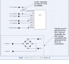
Ok guys I will try to explain the thingy/T-1 This is the throttle 1 = 1amp 2 =2amps so on. Then I'll get a schematic posted. The basic principals of operation is that of a "tone link" 4 tones per each T-1 and maximum of 80 tones, max engines 20. The integrated circuit is that of a tone decoder, these devices are members of a family of circuits know as "phase locked loops" each tone is 6% apart to prevent cross talk. The rails carry the tones and the voltage set at 14v. A crystal oscillator is used (digital) to run the system at 3.58 Megahertz. This is is about the fastest we could use with (cmos). The system works from a mixer which take 18v AC from a transformer and rectifies it to dc voltage by means of a LM380 audio amplifier. The tone signals appear on the track as signals with one volt peak to peak amplitude. Key pads are use to control the tones to the T-1 these contain digital electronic circuits and a crystal controlled oscillators and a 20 position switch to control the channel. The T-1 operates from a well controlled build in 5v power supply so not to be affected by track voltage changes. The main part of the control circuitry is an integrator 5v = full fwd, 0v = full rev 2.4 to 2.6 is off. The out put is a combined triangular wave. The T-1 has a H bridge built in it. (very late versions had a L272m IC maybe the answer to my question???)
What has been a problem with it use, is that the T-1 gets hot as most of the time a train is running one direction for a long time.And it burns up. A guy back in 1994 came up with the circuit back in the first post that made the T-1 a preamp and it took all the heat eliminating T-1 failure! The T-2,4 throttles did not have the same problems as they were meant for much larger scale trains and they had the room to make the circuitry much larger and there by able to protect it. I hope this clears some questions. steve
 
Last edited:
To answer ARHI. As best as possible I try to fit all the components in a ho scale train engine which is the DC motor we are controlling. It isn't always easy and once I add a sound unit. Which works the same way via tones. The whole fitting it in the train engine goes out the window.It always goes in a dummy no motor engine, and I feed the output thru a set of wires with a plug, back to the motor. Yes DCC was born in the model RR world around 1993 and it was adopted as the standard. It has 1000's of better options and is 1/10 the size I am using. This is what placed Keller Engineering out of business in 1995.(that's this system)They started this system in 1977. At that time I had 3000.00 dollars invested and wasn't going to walk away from this system. By 2000 most of thousands of Keller users had walked. I was able to buy the system at pennies on the dollar.$55.00 T-1 throttles, $5.00 $125.00 mixers,10.00 $225.00 keypads were $15.00 each. I stocked up! By 2003 I had old users sending all the items free just if I paid the shipping. Now I run the only Keller Onboard Control website for these items. I refuse to sell any items, as that would kill the hobby aspect, and move me into a Hobby Dealer, which I am not. But I trade with others for same like item. (Train items) Today there are about 100 users world wide I know of.
What started this mission was I started to add engines to my layout after not buying any since 1995 time frame and because of DCC, companies started to make more room for components. Great! but for me just not enough yet. I still have to Mill out pockets to fit that darn H bridge or run the parts all over the place and wire it up. The good part is the 12oz lead weight acts as the best heat sink ever. steve
 
Last edited:
Arhi and Roff and others I think I need to provide more information. I just not sure what it might be. Arhi said maybe a L293 Roff says it requires a digital input, won't work? Now I'll try this again this unit as is works. I wanted it smaller. I was looking as the throttle schematic and it has a L293 on it? I was also thinking I have found many IC that take Analog and convert it to digital. Why would that not work for me If I am sending out analog and I convert it to digital the Dc motor will still work probally better.
https://groups.yahoo.com/group/onboard-keller/files/Throttle/
see if you guys can look at this page. It may enlighten you to something i haven't said? steve
As I said, what I was proposing was the smallest workable solution.

You could get a PWM chip and do the raw speed control and use a hard switch for direction, but it takes more doing. I thought you wanted the smallest convenient solution.

https://www.electro-tech-online.com/custompdfs/2008/12/LM22673.pdf is a reasonably small, easy to use, reasonably priced voltage regulator.
 
To answer ARHI. As best as possible I try to fit all the components in a ho scale train engine which is the DC motor we are controlling. It isn't always easy and once I add a sound unit.

Thanks for the explanation, and for the T1 schematic followed with good explanation. All in all, You control the onboard devices by tone that is modulated into the tracks. You extract the tone using few LM567 (LM567 is kinda discontinued, there might be some "better" chips out there) and then do a whole mambo jumbo to implement the "recognised command".

What you can easily implement is replacement circuit that will do the whole chabeng digitally without changing the drive electronics. What I'm talking about is replacing the whole T1 + power pax module combination with digital uC controlled circuit. It would be fairly easy and IMHO energy more efficient, to put a small 8 or 18 pin PIC that will get the input from few LM567C (or better tone decoder) and control everything on the train... it is natural for the uC to generate PWM to run the DC motor via L293 or L298, this will reduce the size of the T1+powerpax to 2IC's + few LM567C and few passive elements, much smaller then current elco you have, on top of that, you can change the new decoder/controller uC to decode more then 2 tones and control everything else you need controlling (you might have to move from 8pin to 18pin uC and more lm567C's but that's all) ... The whole thing can be very small if you are able to solder smd :)

Now, I'm not sure how much this changes the philosophy of it all, but your "base unit" that issues the commands is the same, you only change the decoder / implementer unit inside the car... but it will allow you to make pretty efficient and small T1 replacement ... only downside is that it will require some programming knowledge and some soldering skills

EDIT: what UBergeek63 is proposing is IMHO "better immediate solution" that will do exactly what you need, what I suggest is to replace "too much" in order to replace it with micro controller as I just like micro controllers :) (and am terrible in simple analog electronics)
 
Last edited:
Hey guys thanks for all the response. I hope LM22673 will work that UBergeek63 has pointed me too. I sure hope I will be able to figure out where my input wires go and come back out? If any of you can help me out it would save me a bunch of time. I really am having a bunch of fun searching post and finding new things .steve
 
You could also use the H-bridge booster you have always been making except get rid of the BR (diode bridge rectifier). If you use the BR at pins 6 and 8 on the T1 instead, you will have that much more space.
 
Sorry this took so long...what is the signaling method? Are you sending PWM or FM as the speed control?

Now I have actually looked up a few sites on "DCC", and I still am not sure what the control format is. It does not seem like yours is a "DCC" anyhow. I think I could sneak a motor control into an N gauge, but the receiver would be problematic. Not a problem with your HO.

Dan
 
Dan, This system is not "DCC" Its origin dates from 1979 the size of the T-1 is .700W 1.375L and 3/8H Its huge by todays DCC standard. I just haven't made he move to DCC as I have too much of the old system that just runs fine. I just wanted to make the Booster (H bridge) smaller.This system is analog by most terms. I am going to put it on a scope and see the true output. None of this had any meaning to me till I open this can of worms. I had never looked into why it worked , just that it did work! While room is a factor it isn't the only factor. I was hopping to just be able to take one IC and wire in line with the T-1 and go.There by saving building the circuit all together.So I miss lead some by saying it needed to be smaller, I should have said easier as well. I have since made contact with the original person who first showed us this boost(H bridge) He has pointed out he never built it on a circuit board as it became to big to fit in some HO models. But he placed all the components threw out the engine screwing the Transistors
to the lead weight inside the HO engine. I forgot to ask if all 4 transistors can be placed on the same lead weight or will there be a short?
steve
Well I can get it into an HO with relative ease, assuming there is space to put it in.

Do you mind a drastic change and how many things do you want to control?

Dan
 
Dan What are you proposing the complete rebuild of the T-1 ? Each T-1 now only controls FWD/REV Bell/Horn along with diesel sound 4 tone each channel total of eighty tones total of 20 engines. I am not sure where your going? steve
 
Last edited:
Dan What are you proposing the complete rebuild of the T-1 ? Each T-1 now only controls FWD/REV Bell/Horn along with diesel sound 4 tone each channel total of eighty tones total of 20 engines. I am not sure where your going? steve
As my last exposure to model trains was and unregulated power supply from a variable transformer, I do not know what T-1 is with out looking it up. The best solutions come from complete understanding of what there is to work with: standards, exsisting equipment, and readilly available affordable parts.

Are the forward and reverse tones PWMed?

Dan
 
Ok Dan I will get that info. Post 13 of this thread shows what a T-1 is.(schematic)
steve
I saw. It is not clear how it is being used. You see, those chips can use the same components and drive analog or PWM depending on the signal source. It is essentially the difference between Frequency Modulation and Pulse Code Modulation also know as On Off Keying in the ham radio world.

Dan
 
Dan I am almost sure it a analog signal.As per the book it send pulses to the motor allowing the motor to coast between these pulses. Now that being said the T-1 on older version does this through a H Bridge used strictly as switches , either fully on or off! On later versions this comes from a L272m same thing just a IC. This is where I got the idea of using it (L272)as my booster. Ccurtis has send me a schematic to try this out.
 

Attachments

  • h-bridge(2).JPG
    h-bridge(2).JPG
    60.3 KB · Views: 171
Dan I am almost sure it a analog signal.As per the book it send pulses to the motor allowing the motor to coast between these pulses. Now that being said the T-1 on older version does this through a H Bridge used strictly as switches , either fully on or off! On later versions this comes from a L272m same thing just a IC. This is where I got the idea of using it (L272)as my booster. Ccurtis has send me a schematic to try this out.
That is a crude PWM then, good.

DO NOT, I repeat DO NOT use a L272! With over a 1.5V drop per switch at 0.5A you are dissipating 1.5W into 100C/W for 150C, not reliable under any circumstances and certainly not something you want inside you plastic HO engine!

The reason is it is a bipolar output drive with a 1.5V drop instead of a mosfet with minimal Rds on for a very low saturation drop and it's associated low heat build up. (no matter how good everything else is the heat needs to go somewhere)

Dan
 
Last edited:
OK Dan than do you have another solution? If not I don't see why not trying it,as there is already a L272 in operation on the T-1. I was planning to use a L272 sip9 with a tab and screw it to a block of lead that surrounds the motor to the HO engine. This is a very lage heat sink.
steve
 
OK Dan than do you have another solution? If not I don't see why not trying it,as there is already a L272 in operation on the T-1. I was planning to use a L272 sip9 with a tab and screw it to a block of lead that surrounds the motor to the HO engine. This is a very lage heat sink.
steve
https://www.electro-tech-online.com/custompdfs/2009/01/3959.pdf $4.75 each from digikey.

At 0.5A on the motor it only dissipates 0.15W (again just the conduction losses) and with synchronous rectification will not likely need any heat sinking at all. Sugject to testing, of course.

Dan
 
Thanks Dan, I want to give it a try. Do I wire it the same as the post 4 up from here? I don't understand all the leads/terms that come off the IC. As first posted I know that the things I follow (copy) work i don't understand why? This item might be the trick but only if I can wire it up to the T-1.
steve
 
Status
Not open for further replies.

Latest threads

Back
Top