ccurtis
Well-Known Member
Tanker, armed now with the knowledge from one of your previous posts that the output of the T1 is purely on-off, this device has all four transistors in the circuit you are presently building in one package. This makes the buffer smaller and easier to put together. It will still need to be attached to metal to provide heat sinking.
https://www.semicon.toshiba.co.jp/docs/datasheet/en/LinearIC/TA7267BP_en_datasheet_070228.pdf
https://www.semicon.toshiba.co.jp/docs/datasheet/en/LinearIC/TA7267BP_en_datasheet_070228.pdf
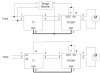
") Looking at the datasheet for the TA7267BP that's about right with boths inputs (3/4 wires) at 14.2 volts.
Looking at the datasheet for the TA7267BP that's about right with boths inputs (3/4 wires) at 14.2 volts.
