Hello,
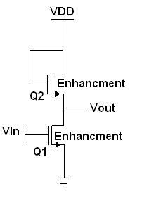
I wanted to try this circuit as an inverter.
I was told that the VOL of this circuit is too high.
I have 3 question please:
1. des 0L region start when the VTC reaches a -1 slope?
2. Why is the VOL here considered high?
3. The VOH of this circuit is VDD - VT2. Is it considered a low VOH? (assuming VDD is 3.3V/5V).
I know I can use better inverters, but i want to understand whats wrong with this one.
Thank you.
Attachments
Last edited:
