Continue to Site

Welcome to our site!

Electro Tech is an online community (with over 170,000 members) who enjoy talking about and building electronic circuits, projects and gadgets. To participate you need to register. Registration is free. Click here to register now.

  • Welcome to our site! Electro Tech is an online community (with over 170,000 members) who enjoy talking about and building electronic circuits, projects and gadgets. To participate you need to register. Registration is free. Click here to register now.

Odd prototying behaviour

Status
Not open for further replies.

Mosaic

Well-Known Member
Hi All:

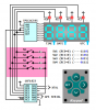
I have a pic 16f886 on a breadboard running a CA, 4 digit via a tpic6c595 shift register. The 7 seg CA display is driven by 2n3906 PNPs to strobe the digits.

I am getting some flicker on the digits and digits that are supposed to be off ghost a bit as well. My display loop is not on an ISR. It's part of the main loop.

The strobe is called every 2 millisecs or less. Between 1 and 1.8ms usually.

That's better than 50Hz, I can't quite see why I am getting flicker.....and ghosting. Do i need a faster refresh?


Also, I am not using Mclr...I need the pin as a digital input. When I first apply power things proceed normally. Then if I power off and on ...the program does not restart from the beginning...it seems to 'remember' where it left off or somehow skip past the start sequence.
I've tried waiting a while but there seems no predictable result...sometimes it works from the start other times it continues where it left off.

Also, I seem to be getting resets every few seconds as well.....Perhaps its all the wires causing interference. I haven't grounded all the unused pins yet., some of which are adc inputs.....should I do that and then test?


Thx..!
 
Do you have the watch dog timer enabled maybe? That would explain the "random" resets.

A large value cap in your power supply could explain the display not resetting after you pull the power.

For the ghosting and flicker, are you changing the display segments before setting the digit output with the 2N3906? That will cause that behavior. The solution is to turn off all digits, refresh the segments and then enable the proper digit.

Posting your code might help others aid in troubleshooting.
 
WDT is NOT enabled. Insofar as the the PIC resetting on power being pulled.....I have PWRTE and brown out enabled.
Further, I have only a .1uf across the PIC Vdd/Vss and when I pull the power I mean I literally disconnect power from the pic VDD pin.
The simulation on Proteus ISIS runs fine. No flicker.


I am suspecting the LVP, the PICKIT2 is using LVP and that means I can't clr the LVP bit in the config. fuses. Now the pgm pin #24 is used as an I/O pin in the program to drive a 2n3906 for digit #4 on the 7 segment. Maybe this is pushing the pic into and out of program mode, causing odd resets and 7 segment flicker. Possibly those same resets could be causing the programming to glitch and skip about making it appear to be starting later than it should based on the 7 segment display.


How can I force the Pickit2 to use HVP so I can clear the LVP fuse and test this?
 
Update:

I fixed the LVP issue and the resets have gone away. Although some weird stuff is still happening that doesn't happen on the sim.
Some of it appears to do with transients glitching the PIC. Also I have to short the PIC Vdd to VSS for a couple secs to get it to restart from fresh otherwise it seems to keep the PCounter alive and restart from where it left off.

It appears that as soon as the PIC goes into data acquisition it starts to glitch. Grounding all the adc inputs didn't help. Have no solution for this yet.

A strange prob that I HAVE isolated but still can't solve is without a massive cap (like 1000uf) on the input of the 7805 vreg there is a high chance that, upon power up, the signal triggering the shift register to display a character loses sync with the Display digit select signal. So all the 7 segments digits look like a blur of 8's.
I verified the sync loss with a scope....by monitoring the digit select clock vs one of the led segments. When they are in sync I can see the segment activate in tandem with the clock....loss of sync is easy to see.


If i place the pwr switch AFTER the vreg and activate it while the unregulated power is applied ...all is well, I just can't switch the main power. This happens running off a 9V battery as the main supply.

I am thinking I may have to place a transistor with a RC pair on it's base to delay power up of the 5V after the main is switched on.


On power up
 
Simulators are not perfect.

It could be that you are seeing the effect of switch bounce when you apply power. Most pics have a config/fuse to delay a bit when power is applied prior to starting the processor. Try enabling it and report back with what problems still remain.

If this circuit is soldered rather then on a solderless breadboard: did you wash the flux from the solder joints. It can do strange things.
 
Hi 3vo:

I have the following (16f886) fuses active:

__CONFIG _CONFIG1, _IESO_OFF & _FCMEN_OFF & _PWRTE_ON & _WDT_OFF & _INTOSCIO & _BOR_ON & _LVP_OFF & _CP_OFF &_CPD_OFF & _MCLRE_OFF &_INTRC_OSC_NOCLKOUT

__CONFIG _CONFIG2, ; left as default

Disabling PWRTE and BOR - brown out makes no difference.
 
Well sometimes the program works and sometimes it doesn't ..... some kind of corruption in the prg upon start up.

I need the program to reinit itself....

Anyone has a sample bit of wdt code?
 
Ok I am TRULY frustrated now.

I enabled the WDT and from the display it seems to reset every 2 seconds or so....BUT the PIC restarts FROM where it left off the PC DOES NOT RESET.

ALSO, I tried the MCLR...same crap...THE PIC RESTARTS WHERE IT LEFT off ...no prg restart.

I figure I have a defective MCU.

I don't know what to do to test this any further.

Perhaps down grade to a basic flashing LED and start building bit by bit from there. WHICH IS freaking me out since I HAVE 6000 working simulated program words.

ONE out of maybe 100 tries I can get it to work reasonably on the breadboard, without a corrupted display.
 
You're not clearing the shift registers as part of your power up routine. The PIC is resetting, your display is not. You need to clk out all blanks on power up or toggle the reset line on your shift registers.

Posting your code makes it easier for others to help with non hardware related issues.
 
Well, it's true I am not clearing the shift register. BUT when the code resets it displays a sequence of info about the program config. This ought to restart and not continue where it left off. Therefore MCLR ain't working right.

I do clear ALL the GPR to zero on boot, then copy data config from EPROM into GPR then init the timers & I/O (ADC etc) , then run the config display sequence, then drop into the main loop that takes keypress input.

I will try to strip things down to the display routine with a couple simple keypress responses and a single adc input. Then test it on the 16f886, if no go still...I'll post this prg as it's too complicated as is to post for help with all the calls, bank switching, FSR, Comp goto's etc.

I'll ask for help a chunk at a time ..

I want to isolate the breadboard so I'll do a version to run off the 16f690 LVP ....to keep the PIC on a 'clean' board. I just need to isolate this prob.!
 
What value are the current limiting resistors?
You must clear each display before loading the next, to prevent ghosting.
Do you have a 10u and 100n across the micro?
What value pullups on the switches and maybe noise is getting into the input lines.
 
Last edited:
Maybe it's something to do with this line,

__CONFIG _CONFIG1, _IESO_OFF & _FCMEN_OFF & _PWRTE_ON & _WDT_OFF & _INTOSCIO & _BOR_ON & _LVP_OFF & _CP_OFF &_CPD_OFF & _MCLRE_OFF &_INTRC_OSC_NOCLKOUT

Mike.
 
Update:

The totally weird stuff with the apparent starting in the middle of display routines etc. is fixed.
Turns out that my init GPR routine CALL was (accidentally) commented out, that cost me 2 days.....sigh. A typo....that the compiler was happy with.
Guys I now realise that zeroing all the GPR on startup is critical. Since it seemed all my Sim work had a default 0 GPR on startup ...should have been set to randomise.


Ok....now things start and run predictably.
The ghosting was trickier. I have a routine that does a system voltage check via a voltage divider on the DIGIT #4 of the 7 segment CA PNP transistor driver base resistor. I am using a 9.1k/27k (gnd/Vcc) 1/4 divider in front of the 1K base resistor. This normally does not affect the base drive from the PIC. BUT when I cause the PIC pin to switch to analog input to measure the voltage across the divider the 7 Segment digit 4 flickers on. The solution was to blank the display via the shift register while the adc sample took place and renable it after the pin was switched back to a digital out.

Jolly.

Now I have a question...my spec calls for a smd , logic level ,p channel MOSFET rather than the pnp 2n3906. But I can't breadboard the MOSFET as it is a tiny SOT-6.
The PNP transistor emitter-base junction leaks current back thru the 1k base resistor into my PIC ADC pin. This causes a voltage drop of about 3.9V across the 9.1k where there should be none. The PNP is on a 5V supply. I could use a blocking diode and a pull up on the base, BUT shouldn't the MOSFET make that unnecessary?

Is it a correct assumption that the MOSFET does not conduct significantly thru the SINK/gate junction?
 
Almost afraid to ask but here goes... Would you like to show us your design? We might be able to suggest ways to get that ADC input off of the column driver pin. For example, you only need 5 pins to drive a 4-digit 7-segment display with your TPIC6C595 sinking driver (and that includes driving the four P-FETs). And, you can read up to four switches with one additional I/O pin.

Cheerful regards, Mike
 
Last edited:
Mike:

I do have 2 column drivers still on single duty. But this morning I broke out the magnifier and soldered cat whiskers onto the ssot6 device. Replaced the 2n3906 and used a 1k gate resistor after the 1/4 voltage divider and it works great. Zero leakage.

Mike if this project is successful I may very well license it....and so I have to limit disclosure. I have nearly maxed out the 16f886, there are no free pins, 75% of code space used, 98% of eeprom used, 85% of GPR.

However, I have gone from zero MCU ability 4 months ago to this level with the help of this forum, mainly you. In return wherever I can I will extract working parts of the design to help others here. As i have done with the PWM code snippet and the debounce code for short press, long press, trigger on make and trigger on break, 8 switch, parallel debounce. Your core code sample formed the basis of that work.

I am trying to get funding to launch an innovation incubator in my tiny 3rd world country. Engineers here tend to operate on a buy imported equipment, put down a factory/industry and then do maintenance. Very little local innovation. I hope to make a dent in that and start training graduate engineers to think differently. Your help and that of this forum might just yield life changing results for some folks down here.

thanks again!
 
Last edited:
That's scary!

Maybe it's just me but I never could figure out what you were trying to do with your debounce code. I also wonder about your PWM snippet. Why didn't you just setup the PWM module for a 1-msec period (1-KHz) which could have provided you 250 to 1000 duty cycle steps, all in hardware with no software overhead, and then you'd only have to count ten 1-msec PWM (TMR2) interrupts for the 10-msec period that you need for something else. It's not surprising that you're running out of pins, memory, and possibly even performance on your project.

Sorry! I don't mean to be discouraging. Best luck on your "commercial" project...
 
I am willing to try it if u could get me going, not having done HW PWM b4. But the solenoid I am driving requires the 20-50Hz frequency drive.
 
Last edited:
I would be happy to help (instead of criticizing -- sorry) but I'm confused by the 20-50-Hz frequency thing. You actually need a "variable frequency" PWM signal output?

Anyway, I would like to pass along a circuit I use for driving 4-digit 7-segment displays when you use a driver IC (below). Basically it re-tasks a couple of the column driver lines temporarily for use as <clk> and <dat> lines to load the shift-register during a very short blanking interval at the beginning of each display refresh/update interrupt. The drawing shows the PWM signal driving the <lat> and <oe> pins for complete fade-to-black display brightness control but you could use some other pin (without brightness control) if the PWM pin is already in use.

Cheerful regards, Mike
 

Attachments

  • MacMux 4-Digit 7-Seg.png
    MacMux 4-Digit 7-Seg.png
    25.2 KB · Views: 168
Status
Not open for further replies.

Latest threads

New Articles From Microcontroller Tips

Back
Top