Continue to Site

Welcome to our site!

Electro Tech is an online community (with over 170,000 members) who enjoy talking about and building electronic circuits, projects and gadgets. To participate you need to register. Registration is free. Click here to register now.

  • Welcome to our site! Electro Tech is an online community (with over 170,000 members) who enjoy talking about and building electronic circuits, projects and gadgets. To participate you need to register. Registration is free. Click here to register now.

NPN LED Driver - Why an extra resistor to ground at the Base?

Status
Not open for further replies.

Kian

Member
Hi all,

I looked at a reference design from TI where they showed a NPN led driver.

uiVisGR.jpg


I have 2 questions.

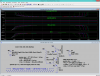
1. What there is a 1.2k resistor (R71) at the base connected to ground. What is the resistor? I don't see this in other NPN designs. Do I need it? If so, how do I calculate its value?

2. I assume R65 is a current limiting resistor to limit the current flowing through the LED. Can it be place before the LED between VCC and the LED? Is there a special reason why is placed at the emitter?

Thanks!
 
R71 is a 'pull-down' resistor which ensures the transistor turns off if the input to R2 is open circuit for any reason. Depending on the voltage applied to the left end of R2, it may also function as part of a voltage divider, perhaps to limit the voltage on Q2 base.
R65, in conjunction with the Q2 base voltage, sets the current through the LED. It also reduces the LED current variation with transistor b-e junction temperature, compared to the variation which would occur in the absence of R65.
 
R71 being a
'pull-down' resistor
also ensures the fast ON/OFF switching of Q2
Discreet LED Test.png
. . . if Q2 so decides
C1 , C2 shape switch ON overshoot , ringing and bypass R3 , R2 for even faster switching
D3 , D4 terminate C1 (somewhat/occasionally reduce the effect of parasitic capacitances in Q2)
R3 , R2 - in principle - set the speed/threshold/sensitivity of the Q2
R1 sets the speed/stability/sensitivity of the Q2
R3 , R1 along with R4 , D2 - can be used to control ON-state current
D5 might occasionally boost the switch OFF as well as not due forward recovery time ← the least also applies to D3 , D4
Q1 (as a reverse diode to the LED - D1) could be justified at high current , high frequency switching + the BJT has quite large parasitic capacitances itself , but if the low capacitance protection diode is used the surge bypass capacitor may also be justified in parallel to D1 , D.Q1
▲▲ the schematic is provided to give one some basic idea of pulse shaping - not that all of it would be a must in all occasions
 
Last edited:
In that circuit I would say R71's primary purpose to act as a voltage divider with R2 to reduce the base and emitter voltage so that a smaller resistor can be used for R65 for a given LED current and allow more voltage to be available for the LED.
A deep blue LED probably requires most of that 3.3V supply voltage to operate.
I assume R65 is a current limiting resistor to limit the current flowing through the LED. Can it be place before the LED between VCC and the LED? Is there a special reason why is placed at the emitter?
Placing the resistor in the emitter makes the transistor a constant-current source, largely independent of the LED's voltage characteristics.
 
Placing the resistor in the emitter makes the transistor a constant-current source, largely independent of the LED's voltage characteristics.
If the LED's voltage is less than (supply-LEDvoltage-R65voltage) then you have a constant current that is NOT dependent on the LED's voltage.

I do agree that a blue LED might take all of the 3.3 volts. (not leaving anything for transistor+E.resistor)
 
I am planning to drive a high power RGBW LED with a BC817 NPN transistor.

The specifications of the RGBW LED is as follows:
Forward voltage (Vf):
Red: 2.25V
Green: 3.3V
Blue/White: 3.1V

Forward Current (If): 350mA

The specifications of the BC817 is as follows:
VCE (sat): 700mV max

I am using 3 AA batteries connected in series as the supply voltage (VCC).

In this case is the emitter resistor calculated as follows?

Re = (VCC- Vf - VCE(sat))/ If

I ended up with the following values for Re:
Red = 4.4 ohms
Green = 1.4 ohms
Blue/White = 2 ohms.

Is my calculation correct?

How should I calculate the value of the base resistor and the one connected to ground for this set of parameters?

Thanks.
 
Why does your transistor have an emitter resistor? As a switch, an NPN transistor has the load and the series current-limiting resistor at the collector, not at the emitter.
Is the 350mA LED current its allowed maximum current? Maybe you should plan on a safer 320mA instead.
LEDs have a range of forward voltage, maybe your values are "typical" then your LEDs might have less forward voltage then your calculations will blow them up.
The saturation voltage of the transistor is a maximum of 0.7V if the base current is 50mA and the collector current is 500mA but your transistor might have less saturation voltage then your calculations will blow up your LEDs.
Three disposable battery cells produce 4.8V when brand new but quickly drop to 3V when used at your high current, then you will see your LEDs slowly dimming until they do not light anymore.
 
Why does your transistor have an emitter resistor? As a switch, an NPN transistor has the load and the series current-limiting resistor at the collector, not at the emitter.

Have you not read the rest of the thread AG?, the resistor in the emitter makes it work as a crude constant current source.

However, I'm with you in that I would prefer the resistor in the collector, the transistor acting as a switch, and moving the heat dissipation from transistor to resistor.
 
Hmm,

So should I have the resistor in the collector or at the emitter? If I need constant current source, then I should put resistor at emitter? If I don't need constant current source, then I am better of putting the resistor in the collector?
 
I need PWM control

Which is still just turning it on and off but with different on and off times.

I would think this would work. Pick your own version of Q1 depending on the gate voltage requirements (I don't think the MMBF170 will work correctly at 3.3V gate voltage). When you select a FET, keep the On resistance spec in mind when selecting the value for the current limiting resistor.

LED1.jpg
 
Last edited:
would prefer the resistor in the collector, the transistor acting as a switch, and moving the heat dissipation from transistor to resistor.
whats the difference when the same resistor moved from collector chain to emitter´s
. . . the ( U.D.led + U.R.cc + U.Q.ce ) = "Const." . . . only due delta I.emitter is now limited by R.cc then everything switching gets slowed down -- mostly cos emitter and base being on the same phase (at turn on the base voltage with respect to GND increases and so does V.Emitter and vice versa at turn off)
so this is why R.cc should be moved to collector incase of PWM
 

Attachments

  • Discreet LED Test - B1.png
    Discreet LED Test - B1.png
    47.1 KB · Views: 152
Last edited:
An MMBF170 Mosfet is rated with a 10V gate to source turn on voltage that is not available with this circuit's much lower battery voltage. Some of these Mosfets barely turn on when the gate to source turn on voltage is 3.0V.
 
An MMBF170 Mosfet is rated with a 10V gate to source turn on voltage that is not available with this circuit's much lower battery voltage. Some of these Mosfets barely turn on when the gate to source turn on voltage is 3.0V.
Which is why I said:

".....Pick your own version of Q1 depending on the gate voltage requirements (I don't think the MMBF170 will work correctly at 3.3V gate voltage).........."
 
Hi all,

I was hoping to seek clarity on the design of a high power LED driver, but it seems like I am now more confused than before having all these various suggestions.

I was just playing around with a BC817 NPN transistor and connected it like what Spudboy488 has suggested except that I am using a NPN BJT. The LED I am using is a XLampXML from Cree:

https://www.cree.com/led-components/media/documents/XLampXML_Color.pdf

I connected only the Green LED portion to the BC817, with a supply of 4.5V coming from 3 x AA Batteries. I have a 2.7 ohm resistor connected to the cathode of the LED and the collector. The emitter is connected to ground. The base is connected via a 200 ohm resistor and to a 3.3V source from a MCU. I tried using a multimeter to measure the current flowing through the LED and it only showed about 50mA. I think i must have done something wrong. It shouldn't be drawing that little current right?

I still don't quite know how to calculate the base resistor. There are some online calculators but I have difficulty reading the required values from the datasheet. For example this link here:

https://www.petervis.com/GCSE_Desig...ator/transistor_base_resistor_calculator.html

The required parameters are Vbe, Vce, hFE, RL, Vcc and Vi.

From the datasheet of the BC817 (**broken link removed**). In page 7, there are 3 graphs for Vbe(sat) and I don't know which one to look at. I presume it doesn't matter that much since they all look the same. Assuming I want to drive the LED at 300mA, this should give me a Vbe(sat) of about 0.7V? Vce is more difficult since the 3 graphs on page looks quite different. As for hFE, its very different for different temperatures and I don't know what value to read from the datasheet. For RL, is this 2.7ohm? Or does it need to include the resistance of the LED too (if it has any)? How do I know what is the value?

Anyone can help?
 
Assuming you don't have an emitter resistor?, but instead have the current limiting resistor in the collector, then you want the most base current you can get - in order to switch the transistor on as fully as possible.

So check the maximum current available from the I/O pin (PIC's are about 30mA or so), subtract 0.7V from the supply to the micro, and use those values to calculate the base resistor. It's really not very critical.

As regards the resistor from base to emitter, you can either leave it out, or use a 10K - or pretty well anything, as it's only there to remove any possible tiny leakage from collector to base of the transistor.
 
Status
Not open for further replies.

Latest threads

New Articles From Microcontroller Tips

Back
Top