Continue to Site

Welcome to our site!

Electro Tech is an online community (with over 170,000 members) who enjoy talking about and building electronic circuits, projects and gadgets. To participate you need to register. Registration is free. Click here to register now.

  • Welcome to our site! Electro Tech is an online community (with over 170,000 members) who enjoy talking about and building electronic circuits, projects and gadgets. To participate you need to register. Registration is free. Click here to register now.

Novice- Need Help! Motorized Display Case Disk.

Status
Not open for further replies.

newbie123

New Member
Hello!

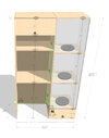
I have no experience with electronics of any kind. I would like to buy or build 3, low profile, motorized rotating display disks for a display case. You can see the mockup for the display case attached.

Ideally, I would have the rotating display disks rotate at a slow pace, controlled by a switch built into the display case. If it doesn’t sacrifice the profile, I would like to have the speed be variable and adjustable by a knob on the swtich, with a high bound cap on the speed. The disks will be supporting a series of statues. The largest of which is Width: 20.5” Height: 22.5” Depth: 17” Weight: 30 lbs. Note that I would just buy a rotating display disk, however they are all to high. I can drill into the ¾ inch wood platform the disks sits on to reduce the height if need be.

My primary questions are:

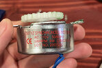
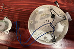
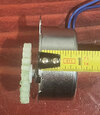
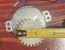
• Ideally, the rotating disk and motor would be less than an inch high, if that isn’t possible, I am wondering what the lowest form factor as possible would be? I am not sure if anyone has any ideas of small form factor motors?

• What are all the parts I would need to buy in order to make this? Do you have any recommendations?

What is the best way to wire everything together?

I am of course open to any and all suggestions, or better ways to build the project. Thank you so much in advance for your time and help, it is much appreciated.
 

Attachments

  • desk mockup plan2.jpg
    desk mockup plan2.jpg
    244.1 KB · Views: 196
Here is how I might do it. Your height limitation is going to be a problem to turn the mass you want. Even if the drive mechanism height is kept small, there won't be enough structure to support the mass.

To get the slow speed and high torque you need, I would use a ring gear at the perimeter of the platform. A custom gear? Not necessary. A DIY gear made from a plywood ring with toothed timing belt glued to the inside.

The platform will be rotated by a timing gear on right-angle gear motor. A critical piece here is that the inner diameter of the plywood ring be such that the timing belt ends meet perfectly – the spacing of the teeth must be perfect.

The diameter of the plywood ring gear and the diameter of the drive gear determine the speed required from the gear motor. Fortunately, timing gears are available in many diameters to allow a range of motor speeds to work. Note – the pitch of the timing belt must match the pitch of the gear.

I didn't show it in my sketch, but a pin and bearing will be needed in the center of the platform to keep it centered.

rotating display.jpg


SmartSelect_20220724-122851_Edge.jpg

SmartSelect_20220724-122957_Dropbox.jpg
 
Cool thanks Nigel, the issue here is that I cant find a mechanical motor that is less than 3/4 high, that is 6V, that can deliver enough torque to rotate 30lbs, that is 1 RPM or less. Do you happen to know if one of those exist? and if not, what the next best option is?

Have you considered you're trying to do something unreasonable?, which is why such things don't exist.

You looking for high power, low speed, and a tiny motor - pretty well all of which contradict each other.

From an initial point of view, I would suggest doing some tests of your planned turntable system - just spinning it by hand initially, so you can get a feel for how well it works, and how much effort it takes to spin with the load on. From that, try different motors, don't worry about size for now - try and find what sort of spec motor does what you want.

You might try looking at capstan motors in old VCR's, they are very low profile, can run quite slow - but more from a point of considering (a bit of a fantasty option) building your own similar type motor, directly as part of the turntable.

If you take one to pieces it's a circle of almost completely flat coils (the stator), and a few hall effect sensors, the bottom of the rotor has a very flat circular magnet, The usually have an on-board control IC, but I suspect they aren't 'that' easy to control?.
 
Here is how I might do it. Your height limitation is going to be a problem to turn the mass you want. Even if the drive mechanism height is kept small, there won't be enough structure to support the mass....
Thank you FTP- I think this might work as well, alot more work than I anticipated but I think you are on to something here. I will definitely look into this and thanks again.
 
If you give this a try and don't have a means of cutting the ring accurately, try to find access to a laser cutting. A maker space might offer the service, or a commercial vendor. Two or even 3 layers of plywood might be required to get the thickness. Make some test cuts to dial in the diameter needed.
 
Have you considered you're trying to do something unreasonable?, which is why such things don't exist....
Hey Nigel,

Yes and thank you- I have considered that this is unreasonable. Which is why I am asking about it as I have no experience. I do know that rotating 30lbs at less than 1RPM is possible, as you can buy a display off the shelf that can accomplish that. The only issue is that typically, the profile is larger than 3/4 inch. Such as this one which is just under 2 inches tall.
So my challenge here was to find the aforementioned that is 3/4 inches tall. I figured that was possible- but maybe not. I have a tendency to believe things are possible. Especially considering the display previously mentioned is less than $30, and made of cheap materials from China, I figured reducing the space with more streamlined parts, or a better, different configuration was a reasonable thing to look into.

Thank you for the advice on testing things out- I have taken apart the aforementioned motor to see how it worked and tested things with that motor (some images attached) The way this motor woks is similar to what FTP mentioned in his previous post. I plan to do more testing- the issue I am having here is that I want to be sure I buy the right parts before starting. I really like the idea of trying different motors- the capstan motor seems promising. I know nothing about motors and electricity really so I just want to make sure I test appropriately. For example, how do I limit the high bound RPM of a DC motor? Which motor can handle 30lb of load? What is the smallest profile motor than can handle 30lb of load? What is the best switch to use to connect all three motors and vary their speed globally? etc. etc. Anyway I appreciate your candor here, and I will definitely do some testing, just want to make sure I have the right parts to test. Thanks again, your input has been invaluable.
 

Attachments

  • IMG_1709.jpg
    IMG_1709.jpg
    64.2 KB · Views: 173
  • IMG_1710.jpg
    IMG_1710.jpg
    98.9 KB · Views: 166
  • IMG_1712.jpg
    IMG_1712.jpg
    85.4 KB · Views: 170
  • IMG_1716.jpg
    IMG_1716.jpg
    59.8 KB · Views: 164
  • IMG_1718.jpg
    IMG_1718.jpg
    59.1 KB · Views: 165
  • IMG_1725.jpg
    IMG_1725.jpg
    65.9 KB · Views: 166
  • IMG_1727.jpg
    IMG_1727.jpg
    56.7 KB · Views: 170
  • IMG_1730.jpg
    IMG_1730.jpg
    60.1 KB · Views: 163
Last edited:
There are some different ways to configure the basic principle I have presented.

One would be to use a round tubular belt, on the outside of the plywood ring, with the gear motor positioned in the back corner of the shelf. This might allow the bulk of the shelf to be thinner (still probably not as thin as you'd like) with the motor being thicker in the corner.

An advantage of this is the the exact size of the plywood ring isn't critical. A groove for the belt would be easy with a stack of laser-cut pieces.
 

Attachments

  • SmartSelect_20220724-141534_Edge.jpg
    SmartSelect_20220724-141534_Edge.jpg
    71.1 KB · Views: 160
  • SmartSelect_20220724-141549_Edge.jpg
    SmartSelect_20220724-141549_Edge.jpg
    50.6 KB · Views: 161
  • SmartSelect_20220724-141355_Edge.jpg
    SmartSelect_20220724-141355_Edge.jpg
    94.8 KB · Views: 157
To get the slow speed and high torque you need, I would use a ring gear at the perimeter of the platform. A custom gear? Not necessary. A DIY gear made from a plywood ring with toothed timing belt glued to the inside.

The platform will be rotated by a timing gear on right-angle gear motor. A critical piece here is that the inner diameter of the plywood ring be such that the timing belt ends meet perfectly – the spacing of the teeth must be perfect.

That's functionally back to the timing belt reduction setup I detailed in post #16, except mine was purely off-the-shelf parts.

The whole thing can easily be built in the specified heights.
 
I wasn't trying to take credit for or take anything away from your suggestion; it was so long ago I read it that I had forgotten about it. I just said something now because there was about to be a crash with reality!
 
I wasn't trying to take credit for or take anything away from your suggestion; it was so long ago I read it that I had forgotten about it. I just said something now because there was about to be a crash with reality!
No problem, never thought you were. There have been so many posts in quick succession it's difficult to keep track & not miss stuff!
 
To support the platform, something like this "ball transfer" from McMaster-Carr might work well. Three of these positioned near the rim of the platform would provide solid support even if the mass on the platform wasn't completely centered.

These are available in many different types and sizes.

View attachment 137949

Having used those type bearings in a work situation, for something just rotating I'd never use them. Unless you can put a groove on the bottom of the platter to guide it. Any off balance off center of the item on the platter will make the platter walk out of a circle.

To keep it rotating in a circle pattern I'd get "lazy susan" bearing rings. They can't move except in a circle. Just something to show what I mean.
 
I just had an idea about this that may solve the height issue – drive all three platforms with a common motor.

1. Mount each turntable with a 'lazy susan" bearing and some form of large, external-toothed gear. Could be square-type teeth for a toothed timing gear, or even a toothed bicycle gear and chain.

2. In one of the back corners, position a vertical shaft running the height of the three platforms, with a small diameter gear to rotate each platform.

3. Probably in the other back corner, position the motor, with appropriate gears on the motor shaft and the 3-turntable drive shaft to rotate the platforms. Adjust the gear diameters to get the desired speed.

Two points:

1. Remember thrust bearings on the drive shaft to keep it in position.

2. Motor will need to be beefy due to the inertia involved.

This arrangement keeps the shelves as thin as possible while allowing space for the motor drive belt.

A possible downside is that all three platforms rotate at the same speed (although some range could be achieved by selecting different gears for each platform.
 
Status
Not open for further replies.

Latest threads

New Articles From Microcontroller Tips

Back
Top