Continue to Site

Welcome to our site!

Electro Tech is an online community (with over 170,000 members) who enjoy talking about and building electronic circuits, projects and gadgets. To participate you need to register. Registration is free. Click here to register now.

  • Welcome to our site! Electro Tech is an online community (with over 170,000 members) who enjoy talking about and building electronic circuits, projects and gadgets. To participate you need to register. Registration is free. Click here to register now.

Novice- Need Help! Motorized Display Case Disk.

Status
Not open for further replies.

newbie123

New Member
Hello!

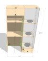
I have no experience with electronics of any kind. I would like to buy or build 3, low profile, motorized rotating display disks for a display case. You can see the mockup for the display case attached.

Ideally, I would have the rotating display disks rotate at a slow pace, controlled by a switch built into the display case. If it doesn’t sacrifice the profile, I would like to have the speed be variable and adjustable by a knob on the swtich, with a high bound cap on the speed. The disks will be supporting a series of statues. The largest of which is Width: 20.5” Height: 22.5” Depth: 17” Weight: 30 lbs. Note that I would just buy a rotating display disk, however they are all to high. I can drill into the ¾ inch wood platform the disks sits on to reduce the height if need be.

My primary questions are:

• Ideally, the rotating disk and motor would be less than an inch high, if that isn’t possible, I am wondering what the lowest form factor as possible would be? I am not sure if anyone has any ideas of small form factor motors?

• What are all the parts I would need to buy in order to make this? Do you have any recommendations?

What is the best way to wire everything together?

I am of course open to any and all suggestions, or better ways to build the project. Thank you so much in advance for your time and help, it is much appreciated.
 

Attachments

  • desk mockup plan2.jpg
    desk mockup plan2.jpg
    244.1 KB · Views: 290
A small DC motor and speed control are simple.
The hardest part is the mechanics to get really smooth rotation with a load on top.

I'd suggest an off the shelf turntable such as these:


Then add a geared motor hidden behind the turntable with a belt drive around the periphery - a length of miniature timing belt & some spring tension, or a giant rubber band.

You may need to add a strip of something around the lower [fixed] half of the turntable to prevent the belt drifting down as it runs.

Or, build it up out of eg. acrylic plastic discs on a centre spindle with a bearing spider such as used in some microwave ovens - a free rotating part with arms that have bearing rollers on the end, for the rotating disc to ride on. Or several bearing wheels in fixed supports around the area.

Again, belt drive to either the periphery or a smaller disc under the main one, concealed by a semi-circular fixed part at the front.

I don't see any way of getting a really low profile in a totally self-contained turntable, as the motor and gearbox need to be reasonably large.

Another option would be have the motor inside the turntable area but sunk through the shelf; it could be concealed in the compartment below by a display light.
eg. Something like a basic style HiFi turntable drive.
 
Wow thank you rjenkinsgb!

I appreciate the turn table recommendations- I have looked at those thoroughly. I am hesitant to use a belt as that will be more difficult to conceal. However the idea of a center spindle with a bearing spider that is sunk into the motor inside the shelf seems like a great low profile option- I could use a dado cut of some sort there and reinforce it on the underside of each platform. Unless you think there is a better one? I am really curious to hear your thoughts on what actual parts I should consider to build this, in addition to where the best place to buy these items would be? Thank you again in advance for your time and help, it is much appreciated.
 
The only motor I can think of that might be a low enough profile is a microwave turntable motor.

If the shaft of such a motor engaged with an inner ring lined with rubber then it should be geared down enough to produce a very slow rotation. Varying the inner ring size would vary the speed.

Mike.
 
Ok thank you mike m! Now to go find a microwave :)
It's essentially a clock motor, I've replaced countless of them - usually stripped gears, noisy, or spillage inside the oven running down the motor shaft. Just a tip, later ones often weren't accessible (no screws), and you had to cut the cover plate off the bottom (pair of big side cutters), then rotate it to refit using your own screw(s).
 
Thank you to all who have replied thus far! It has been insightful to say the least. Due to all of your great input, I have what I believe to be a more sound design (attached). My main concern is still the size of the motor. I am thinking a small DC motor, that has 1 RPM. It is for a display so the thing is great if it's slow. As stated, it has to turn a 30lb statue, with a height of less than .75 inches. I looked into microwave motors, which would work well- many are just .4 inches tall, but they cant turn 30lbs. If anyone has any links to motors they think will work it would be much appreciated.
 

Attachments

  • rotating display disk mockup.jpg
    rotating display disk mockup.jpg
    315.4 KB · Views: 269
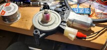
You might consider an automotive power seat motor as shown in the picture – many models of cars use something similar.

They will be thicker than you'd like, maybe 3" thick, but they will rotate a huge mass. They'll run over a large voltage range so the speed can be controlled over a range; if I recall correctly, the speed range would be suitable for a display. I did some tests on one of these I got at an electronics store but don't remember the details.

SmartSelect_20220715-085905_Edge.jpg
 
Here's a video of one of the electric seat motors in action. Let's make it two videos. The first is with ~12 VDC supplied. Probably too fast for a display case!

The second is taken with 1.8 VDC supplied. The motor is drawing three-quarters of an amp to make a rotation in 8 seconds. At this voltage, I cannot stop the motor from spinning or even affect its speed by trying to grip the shaft with my fingers.

Overall dimensions are less than 5" x 7" and about 2" thick to the top of the spindle.

Crap – apparently videos aren't allowed, so a photo is attached.

20220716_153911.jpg
 
Here's a video of one of the electric seat motors in action. Let's make it two videos. The first is with ~12 VDC supplied. Probably too fast for a display case!

The second is taken with 1.8 VDC supplied. The motor is drawing three-quarters of an amp to make a rotation in 8 seconds. At this voltage, I cannot stop the motor from spinning or even affect its speed by trying to grip the shaft with my fingers.

Overall dimensions are less than 5" x 7" and about 2" thick to the top of the spindle.

Crap – apparently videos aren't allowed, so a photo is attached.

View attachment 137865
Holy cow thank you Popcorn- this would work and is a great idea- the problem is its just too large. Thank you for this info though, if only I had a shrinking ray :)
 
Gearing can be accomplished as I outlined in post #4 or use a gear ring and pinion. The weight of the object shouldn't matter except for accelerating/slowing down as long as good bearings are used and no out of balance weight is present.

Mike.
 
I still think your best bet is a belt drive.
eg. see these:

A flat plate turntable with a 120 tooth pulley attached (eg. glued or screwed through) & fitted over a fixed, slightly recessed spindle. (Recess to take the pulley boss, unless you remove that).

Use ten to twelve small sealed ballraces fitted to "u" brackets or pairs of "L" brackets as support wheels at regular intervals on the base, distributed on two different diameters under the turntable plate (outside the pulley area).
eg.
or

Using a 6mm plate, 10mm bearings with 2mm clearance below, that can give a top height as low as 18mm. Or 20mm with an 8mm plate.
I'd try to keep the bearings on an original uncut surface for accuracy, though you could recess them if you needed a lower profile and can accurately mill the entire area.

Or use straight axles rather than brackets, with the axle attached or clamped to the original surface and just the bearings themselves over pockets?? [pieces of threaded rod with nyloc nuts to lock the bearings in place?]

You could also put the bracket or axle on thin rubber to reduce any possible noise transfer to the structure.


Then use a small geared motor with the smallest timing pulley somewhere behind the main one, either outside the turntable or underneath the rear of it.

You can use a geared motor with a 90' output shaft to minimise the height and make it easier to conceal.
eg. The single shaft versions of these are under 18mm high to the top of the shaft. You can recess the motor slightly to match the pulley height to the turntable.

Decide the possible motor to turntable spacing range, then find a suitable timing belt length that suits and go from there to set the final position, allowing for a small adjustment range.

With 16:120 timing pulley ratio, that reduces the 4-16 RPM motor to more like 0.5 - 2 RPM.

A fixed curved skirt around the front would conceal the belt etc. below the turntable; or it could be attached to the turntable if the motor is within the profile of the turntable.

As long as you are very careful with the bearing heights and the turntable is absolutely flat, the load mass should not matter too much, the motor only has to overcome friction once the item is rotating at the required speed.
 
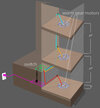
Thank you everyone for your thoughtful replies, as I move forward on this project, I realized I have no idea how to wire the motors together? I will be running three worm gear motors on three platforms, 24 inches apart from each other, then running that into a cabinet that ahs a switch and an outlet to the wall. My question is- what type of wire / gage would I need? How do I connect them together? Should I connect them before connecting to the switch? Does anyone have any recommendations on a switch type? Is there anything else I need to make this work? (i.e like variable speed if possible- anywhere from .1 to 3 rpm- Ideally the switch would turn on all three motors at once, but that is not required.) What type of wire should I take to the power strip? Is there any instructional video on this type of thing as I don't want to electrocute myself lol :) I have attached an image with a mockup for visual. I am also open to any better way / idea to hook this all up if anyone has any thoughts. Thank you all again in advance!
 

Attachments

  • rotating display disk wiring mockup.jpg
    rotating display disk wiring mockup.jpg
    294.7 KB · Views: 271
I suggest you select the 6V motors and use a 6V power supply (wall wart) to power them. The link doesn't mention what current is required but I doubt the start current is more than 1A so a 3A supply should suffice. Almost any wire will do but a good supply would be from an auto shop to carry 12V at >1A (most is rated at 10A). Note that 3RPM is very fast for something of that weight and is very likely to fly off.

Mike.
Edit, note: 6V is perfectly safe to work with. So, if you use a wall wart then electrocution is impossible.
 
Status
Not open for further replies.

Latest threads

New Articles From Microcontroller Tips

Back
Top