Continue to Site

Welcome to our site!

Electro Tech is an online community (with over 170,000 members) who enjoy talking about and building electronic circuits, projects and gadgets. To participate you need to register. Registration is free. Click here to register now.

  • Welcome to our site! Electro Tech is an online community (with over 170,000 members) who enjoy talking about and building electronic circuits, projects and gadgets. To participate you need to register. Registration is free. Click here to register now.

Novice- Need Help! Motorized Display Case Disk.

Status
Not open for further replies.

newbie123

New Member
Hello!

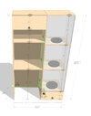
I have no experience with electronics of any kind. I would like to buy or build 3, low profile, motorized rotating display disks for a display case. You can see the mockup for the display case attached.

Ideally, I would have the rotating display disks rotate at a slow pace, controlled by a switch built into the display case. If it doesn’t sacrifice the profile, I would like to have the speed be variable and adjustable by a knob on the swtich, with a high bound cap on the speed. The disks will be supporting a series of statues. The largest of which is Width: 20.5” Height: 22.5” Depth: 17” Weight: 30 lbs. Note that I would just buy a rotating display disk, however they are all to high. I can drill into the ¾ inch wood platform the disks sits on to reduce the height if need be.

My primary questions are:

• Ideally, the rotating disk and motor would be less than an inch high, if that isn’t possible, I am wondering what the lowest form factor as possible would be? I am not sure if anyone has any ideas of small form factor motors?

• What are all the parts I would need to buy in order to make this? Do you have any recommendations?

What is the best way to wire everything together?

I am of course open to any and all suggestions, or better ways to build the project. Thank you so much in advance for your time and help, it is much appreciated.
 

Attachments

  • desk mockup plan2.jpg
    desk mockup plan2.jpg
    244.1 KB · Views: 196
Do you have any particular motors selected yet? That determines the voltage and current required.

Also important: the listed motor current may not include the starting current, which can be several times higher. The "wall wart" powering the motors may need to be capable of supplying 3× the run current. Switching power supplies (the common type in wall warts) respond to being overloaded by cutting the output voltage. If the starting current of a motor is too high, it will hiccup – it will start to speed up, then shut off when the power supply shuts down.....again and again and again.
Hello FTP,

Yes this is the motor:


Thanks for the tip- I dont know what I am doing here so any advice on which wall war tto use and motor to use would be a huge help. Thanks in advance, I appreciate it.
 
I suggest you select the 6V motors and use a 6V power supply (wall wart) to power them. The link doesn't mention what current is required but I doubt the start current is more than 1A so a 3A supply should suffice. Almost any wire will do but a good supply would be from an auto shop to carry 12V at >1A (most is rated at 10A). Note that 3RPM is very fast for something of that weight and is very likely to fly off.

Mike.
Edit, note: 6V is perfectly safe to work with. So, if you use a wall wart then electrocution is impossible.
Thanks Mike. I appreciate your great response- When you say "3a" are you referring to the wall wart? Do you have a link to a wall wart you recommend? Also, do you have a switch you recommend that can control all three motors and then connects to the wall wart? Not sure if thats the best way to connect everything. Anyway thanks again Mike.
 
One problem will be finding a beefy 3 volt power supply for those motors. 5 volt supplies are common for USB devices, 6 volt and 12 volt supplies also common. With a motor designed for higher voltage, lower current will be required to get the same power from the motor.

The power supply will have positive and negative connections, which will be connected in parallel to all three motors.

I suggest switching the AC input (line input) to the power supply unless you may want to control the motors individually.
Hey FTP, the idea I had was to connect these motors to a wall wart- will a power supply still be needed in that case?
 
"Wall wart" = power supply = 120 (or 240*) VAC to low voltage DC (whatever voltage the motors need),

* Line voltage depends on where you are.
 
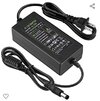
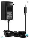
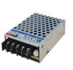
Power supplies can be in many forms – here are a few examples. The type with an attached or plug-in line cord would probably be best to reduce the line voltage connections to be made.

SmartSelect_20220724-000033_Amazon Shopping.jpg

SmartSelect_20220724-000056_Amazon Shopping.jpg

SmartSelect_20220724-000007_Edge.jpg

SmartSelect_20220723-235937_Edge.jpg
 
Power supplies can be in many forms – here are a few examples. The type with an attached or plug-in line cord would probably be best to reduce the line voltage connections to be made.
Hey FTP, If I got these motors, and used this speed controller, would that work? The speed controller is only rated for 6 to 28 volts, but the motor is only 3 volts... will that still work? Also, I am wondering how I limit the high bound of the RPMs on the motor as I don't want to go over 1RPM... Sorry for all the noob questions I don't know what I am doing lol, and thank you for your help.
 
Why are you considering the 3V motor. The link shows 6V motors as well and one that runs at 35RPM. A 6V supply will be far easier to find than a 3V and a speed controller is more likely to work (Note, the speed controller you linked to starts at 6V - not 3).

Mike.
 
Hey FTP, If I got these motors, and used this speed controller, would that work? The speed controller is only rated for 6 to 28 volts, but the motor is only 3 volts... will that still work? Also, I am wondering how I limit the high bound of the RPMs on the motor as I don't want to go over 1RPM... Sorry for all the noob questions I don't know what I am doing lol, and thank you for your help.
(Cross post with Pommie)

That controller might not work below 6 V. However, you could supply the controller with 6 V and as long as you run the controller at less than half speed, you would not exceed 3 V on average to the motor.

I would not recommend running simple dc motors at less than about 20 % of their rated speed. Where low speed running is needed, some form of speed feedback is almost always used. A simple speed controller like that will just put out a lower average voltage to the motor, and that will result in less torque, so starting can be a problem.

You would be better to arrange the gearing to give a lower maximum speed.
 
Why are you considering the 3V motor. The link shows 6V motors as well and one that runs at 35RPM. A 6V supply will be far easier to find than a 3V and a speed controller is more likely to work (Note, the speed controller you linked to starts at 6V - not 3).

Mike.
Thanks Mike- the reason I am considering a 3V motor, is due to a number of reasons- namely, I only need the motor to run .1 to 1.5 RPM at the most. The motor will be used for a rotating display, and will need to turn a 30 lb. weight. The 6v motor is 30 RPM, and I figured it would be more difficult to relegate down to less than 1 RPM. However I may be wrong there. With that in mind, which motor do you recommend? Thanks again for all your help.
 
(Cross post with Pommie)

That controller might not work below 6 V. However, you could supply the controller with 6 V and as long as you run the controller at less than half speed, you would not exceed 3 V on average to the motor.

I would not recommend running simple dc motors at less than about 20 % of their rated speed. Where low speed running is needed, some form of speed feedback is almost always used. A simple speed controller like that will just put out a lower average voltage to the motor, and that will result in less torque, so starting can be a problem.

You would be better to arrange the gearing to give a lower maximum speed.
Thank you Diver,
This motor needs to drive a rotating display that will be supporting 30lbs. I need it to rotate very slowly- and the physicals size of the motor needs to be less than 3/4 of an inch. I am happy to run 6v, but I will need to reduce the RPMs to less than 1. Do you have any recommendations on how to proceed? Or any alternative motors that fit that bill? Thanks again in advance Diver, I appreciate the help.
 
Looking at your original pictures, have you considered thicker (hollow) shelves, with the motor and gearing etc. inside the shelves.

As for running 6V motors off 6V, you simply need the correct gear ratio - attempting to run at a slow speed by using a lower voltage is fraught with issues, and means you will probably need bigger motors.
OK thanks Nigel- in that case, I will get the 6v motor, however do you have any recommendations on how to reduce the RPM on that rotating to less than one? I could use a potentiometer, however is that recommended as I am reducing the RPM by a great deal.
 
Hold off on ordering anything just yet. You've got a challenge to rotate a lot of mass at slow speed. You need the drive system to give you the speed you want – you won't be able to vary the speed with something as simple as a pot.

I think you're planning on supporting the rotating platform solely from the motor/gearbox shaft. That's not going to work very well with so much mass that may not be centered exactly over the motor/gearbox access. So first problem: providing a low-friction support for the rotating platform.

Once that is sorted, the drive system is the next consideration. You may be able to find a gear motor to provide the speed you want; Amazon is probably the wrong place to find this.


I think Nigel is probably right. I think you will need a thicker shelf. Basically a box with a strong bottom to support everything, a top with the rotating platform flush or nearly flush with the top and sides to make it look like a solid piece.

An idea that might work well is coming together in my head.
 
To support the platform, something like this "ball transfer" from McMaster-Carr might work well. Three of these positioned near the rim of the platform would provide solid support even if the mass on the platform wasn't completely centered.

These are available in many different types and sizes.

SmartSelect_20220724-111653_Edge.jpg
 
To support the platform, something like this "ball transfer" from McMaster-Carr might work well. Three of these positioned near the rim of the platform would provide solid support even if the mass on the platform wasn't completely centered.

These are available in many different types and sizes.
Unfortunately I cant do a box as I have a height limitation on the display area. This is going in an office that wont allow over 79" tall on the overall case, and I need each display area to be at least 24". I do however, have the platform supported by a radial bearing. As seen in the attached. Do you feel like that would suffice, or would the ball transfers still be required?
 

Attachments

  • rotating display disk mockup.jpg
    rotating display disk mockup.jpg
    315.4 KB · Views: 168
OK thanks Nigel- in that case, I will get the 6v motor, however do you have any recommendations on how to reduce the RPM on that rotating to less than one? I could use a potentiometer, however is that recommended as I am reducing the RPM by a great deal.
No, you can't use a potentiometer - use mechanical gearing.
 
No, you can't use a potentiometer - use mechanical gearing.
Cool thanks Nigel, the issue here is that I cant find a mechanical motor that is less than 3/4 high, that is 6V, that can deliver enough torque to rotate 30lbs, that is 1 RPM or less. Do you happen to know if one of those exist? and if not, what the next best option is?
 
Status
Not open for further replies.

Latest threads

New Articles From Microcontroller Tips

Back
Top