bountyhunter
Well-Known Member
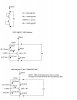
VBE MULTIPLIER: BASE CURRENT AND RESISTOR CURRENT TEMP ERROR EFFECTS
Old time designers know VBE multuipliers do have temp errors due to the effect of base current and resistor current when compared to the voltage of an actual VBE curve over temp. To illustrate this, I attached an example using standardized values for VBE and resistor values. All VBE's will be assumed to be 0.650V at 20C temp and the tempcos will be -2.00mV/C for all devices. This example is simply to illustrate the error effect of the base current and resistor current of the VBE multiplier transistor.
The bias current through the diode connected transistors as well as the VBE multiplier is assumed to be 65mA as it is in the OP's circuit.
In the diode connected transistors, they are diodes so their total voltage drop VB for this example is 0.650 x 2 = 1.300V at 20C. At a typical hot operating temp of 80C, the VBEs would drop by a total of : (.002 X 60 x 2) = 0.24V, which drops VD down to 1.060V @ 80C temp.
In the VBE multiplier, it's more complicated. I split the 65mA current with 20mA down the resistor side and 45 mA down the transistor's collecter side. I will assume a current gain of 50 for the NPN device, which may be generous considering the VCE is dropping to about a volt, but we will pretend it will stay that good for the example.
About 0.9mA of base current is required for 45mA collector current, leaving 19.1mA for the resistor current from base to ground. To get the 0.65V there, the resistor must be 34.0 Ohms. Not a standard size, but we will use the exact value for accuracy in the comparison. Since the full 20mA flows in the upper resitor and we need a 0.65V drop there, it must be 32.5 Ohms. So, at 20C, the VBE multipler has 1.300V across it same as the diode connected transistors.
At 80C you will see the error term come in:
The VBE change due to temperature increase is:
0.65 - (.002 x 60) = 0.530V
However, the current through the transistor's emitter increases by about 3.5 mA since the current through the resistors drops so the VBE increases about 2mV from this effect as well.
That makes the VD at 80C = 0.532V
When you go through and solve the circuit, the VB value now comes out to be 1.073V @ 80C as compared to 1.060V for the diode connected transistors. Does an 13mV error do anything? It does in this case. Assume the output is adjusted for 30mA output bias current at 20C. The output transistors have a total of only one Ohm resistance in their emitters. A 13mV change forced across the output devices VBEs and the one ohm of resistance results in an increase of 8 mA (25% increase compared to 20C value of 30mA).
There is another error term that is potentially significant: at hotter temps, the transistor's VCE value approaches one volt meaning the multiplier transistor is getting pushed into saturation so it's current gain will be falling as the VCE reduces. As the base current increases, that pushes the value of VB even higher (farther away from the nominal diode value) because of more voltage drop across the top resistor, adding more VB error compared to the 20C value.
These effects:
1) Change in VBE from increased current density
2) Resistor current change
Are the temperature error terms in a VBE multiplier compared to an actual VBE.
Attachments
Last edited:

")
