Continue to Site

Welcome to our site!

Electro Tech is an online community (with over 170,000 members) who enjoy talking about and building electronic circuits, projects and gadgets. To participate you need to register. Registration is free. Click here to register now.

  • Welcome to our site! Electro Tech is an online community (with over 170,000 members) who enjoy talking about and building electronic circuits, projects and gadgets. To participate you need to register. Registration is free. Click here to register now.

Not enough range

Status
Not open for further replies.
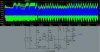
Got some more questions about this circuit here. I put an audio amplifier on the oscillator that Panicmode made.

Is this a good simple amplifier?

Can I put an antenna between L1 and C2, or does it have to be between L2 and C3, cuz the voltage between L1 and C2 is 49 to -21v, and the voltage between L2 and C3 is 0 to 35 volts.

If the voltage goes negative, like 49 to -21 volts, do I get more power, or is it just like 0 to 49 volts?

Is there any way to improve this circuit without getting real complicated? (like putting in 1 or 2 more components) I want this thing to be small. It has to fit in a tiny project enclosure.
 

Attachments

  • 2_coil_fm_transmitter_cad.jpg
    2_coil_fm_transmitter_cad.jpg
    88.2 KB · Views: 293
zach,

Back to original question (bigger range). If you are not sure how to determine oscillator frequency or to tweak it for more output, you might
want to stick to proven designs to avoid frustration. Although circuit I
posted does work, I had to pick values that would work in sim to prove that higher amplitude of the oscillations is possible with minimal change,
so do not use 100uH and 100pF for FM transmitter.
In this case base frequency of the oscillator is only few MHz because
of used LC values.
To get bigger range out of the transmitter you already have, try replacing
transistor in the oscillator for different one or simply make bigger transmitter. Instead of tiny FM oscillator with only few mW of power
you can build one with few Watts of power like this one here:
**broken link removed**
I've built it only few times and it sure kicks a$s but it tends to drift more
than those little transmitters (at least that was my experience).
About checking what's the frequency in the simulator, you have to run it
to get the charts. Right click on the oscillogram and in the bottom
of the popup menu you will notice FFT (fast fourier transformation).
Zoom at the peak of the FFT diagram to read the frequency. You will
notice other spikes like harmonics...
 
Status
Not open for further replies.

New Articles From Microcontroller Tips

Back
Top