Continue to Site

Welcome to our site!

Electro Tech is an online community (with over 170,000 members) who enjoy talking about and building electronic circuits, projects and gadgets. To participate you need to register. Registration is free. Click here to register now.

  • Welcome to our site! Electro Tech is an online community (with over 170,000 members) who enjoy talking about and building electronic circuits, projects and gadgets. To participate you need to register. Registration is free. Click here to register now.

Not enough range

Status
Not open for further replies.

zachtheterrible

Active Member
I was wondering if anyone could tell me what is most likely to cause poor range on this circuit here. It comes in crystal clear over my FM radio until I get about 30 feet away from it. It's supposed to transmit a 1/4 mile.

It's not a bad battery. The transistor is a 2n3904. The funny thing about the transistor is that on the package, it is supposed to have hfe of at least 100. I put it in my multimeter, and it said 16, could this be the problem?
 

Attachments

  • fmtrans_434.jpg
    fmtrans_434.jpg
    265.4 KB · Views: 659
I'm testing one of mine right now as i'm getting a hfe of 140. are you sure your transistor isn't damnaged?
 
I dunno, maybe my meter is off. I got it straight out from the package and put it in a tester to make sure that it was good first, but I'm sure that wouldn't damage it . . . . It's the only thing that I did before I put it into the circuit. Would having an hfe that low cause the circuit to have poor range??
 
First of all, congratulation, you just passed an
important milestone. You can use this experience to
improve your construction.
Transistor with the same part number could (and usually do)
have quite different parameters and especially gain.
That's why for some applications they have to be matched.
Transistor with poor gain can definitelly affect the
amplitude of oscillations and thus range. Gain
decreases with higher fequency in all transistors.
What makes one transistor "high frequency" is ability
to maintain reasonable gain levels as operating
frequency increases. Oscillator is simply amplifier
with positive loop. This means that part of the output
signal is returned to the input of the amplifier to
drive oscillations. If the gain is one, whole output
signal must be used just to keep the circuit oscillating.
As soon as you take part of that signal to do something
else (like drive antena) oscillations will dim to nirvana.
But if you have gain of say 4, only 25% of the output
will be needed for driving oscillator and ca 75% can be
sent to antena (well it's a bit more complicated but
I hope you get the idea).
Bottom line is the higher gain, the more of the signal
is left for use and less is wasted on maintaining oscillations.
Usually max frequency listed in the specs is the highest
frequency that transistor will be able to produce
oscillations - but that's about it. Do not expect
transistor rated at 100MHz to be great choice for
transmitter tuned in 98MHz. You need some safety margin
and for 88-108MHz you should not even consider
anything that cannot oscillate with at least 300MHz.
Except maybe as proof of concept (duh...).
To get better range you will have to experiment a bit.
Why not simply try different transistor? Even different
model. It is also not clear what setup is used in range
mesurement. If you are talking 30feet range through
28feet thick concrete wall filled with metal scraps from
WWII (like submarines, tanks and all other little chunks
of metal), that's not bad range at all... :)
In my experience it is possible to achive ca 1/4mile
or so in open area with NO antena on sender but with short
antena on receiver (ca 2feet). When sender is fitted
with piece of wire as antena, range is bigger off course.
Now don't get too excited because not every single sender
would achive same range. The 2N3904 is supposed to work at
100MHz. According to datasheet it should have gain of 300
at this frequency but remember that gain can be reduced
even for good part if you overheat it while soldering it to PCB.
You might consider real high frequency transistor for Q2
(like 2SCxxxx for Japaneese parts or BFxxx for European).
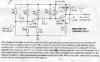
But enough of transistors, I noticed one more thing and that's
the 1k resistor in the emiter circuit of the Q2. In my
designs this was usually 220 Ohm or so and there was another
2.2k resistor from base of Q2 to gnd. Everything else is the
same. You might want to experiment a bit to get the optimum
setup for given transistor. Another option is to put
additional stage (transistor) and amplify RF signal a bit...
 
Zach,
Are you sure that you didn't measure and install the transistors backwards? Their gain will be quite low that way.
Looking at the flat part of the case and with the leads down, the pins are: E B C.
European transistors with BCxxx numbering are the opposite.
 
:(
I thing you have a poor FM modulation.
Your circuit have more AM modulation than FM since the frequency is imposed by L1-C4 resonator circuit and this resonator have the LC parameters unmodified.

The easiest FM transmitter can be make using a capacitor microfone coupled throug a small capacitor with the LC resonator of oscillator.
Another version can be made using varicap diode coupled with LC resonator of oscillator, and this diode develop variations of capacitance when have variations of it reverse voltage. So the audio signal is applied over the polarisation reverse voltage of diode.
 
Thanx so much for taking the time to help me, that was great :D . One thing that I forgot to mention is that I have built this transmitter before w/ the same 2n3904 transistor, and it worked great. I put the transistor in the right way foresure, I even tested it to make sure which lead is which.

I was thinking that the 1k resistor was a little high, I'm going to experiment w/ that after I get it working, but it worked fine w/ the other transmitter. One question that I have though is what would a 2.2k resistor off the base of Q2 to ground do?

While I'm @ it, what is the shortest length of antenna that I could use w/ optimal performance? w/ my research, I came up w/ a 2.34 ft. antenna.

Tavib might also be right. I got the impression that my transmitter was going more AM instead of FM. I took it over to a friend's house who had an oscilliscope. When I talked into it, it seemed like the frequency didn't change (maybe very slightly because it was too fast), but the amplitude of the signal changed. the whole wave would also sometimes go up and down on the screen, which I'm assuming means that the oscillations got more positive, or more negative.


Thanx again :lol:
 
How can you "test" a transistor to see which lead is emitter or collector?
Since they are both a diode to the base, then an ohmmeter will read nearly the same, if the meter is on "diode test" to provide enough voltage.
I guess you could use a current-limited 12V source to see which diode (emitter-base) avalanches at about 6 or 7V, but that might harm the junction.
Or you could use an hFE tester: the right way has a lot more gain.

I still think that the transistors are installed backwards. They might work that way, but not very well.
 
I bought this tester from Radio Shack. You plug it in, and it'll tel you which is which, and if the transistor is good; it also tests scr, fet, diode, etc etc. it's really useful. Neways, I am 100 percent sure that they are put in the right way.

could someone also explain to me this whole thing about my circuit being more AM than FM?
 
Put in a Varactor Diode and it will be More FM than AM. The Varactor changes capacitance with voltage, thus Frequency. The Circuit as posted doesn't do that.

Another Possibility as to the HFE:
HFE is also a function of Current. Those Two Different Multi-Meters may be measuring at different currents and therefore giving different HFE Ratings.

Take care........Gary
 
audioguru said:
How can you "test" a transistor to see which lead is emitter or collector?

I do a "quick and dirty test" with the meter set to diode test, the E-B junction most times will show a higher forward voltage, not much but definitely enough to tell E-B from C-B.
 
I'll try putting in a varactor diode, but I have no idea where to put it. Please explain.

Also, if someone could go into a little more detail as to why my circuit is putting out more AM than FM it would be very helpful
 
chemelec said:
Put in a Varactor Diode and it will be More FM than AM. The Varactor changes capacitance with voltage, thus Frequency. The Circuit as posted doesn't do that.

Another Possibility as to the HFE:
HFE is also a function of Current. Those Two Different Multi-Meters may be measuring at different currents and therefore giving different HFE Ratings.

Take care........Gary
The collector-base junction is reverse-biased through most of the oscillation cycle, and the junction capacitance varies as a function of voltage, i.e., it is a varactor. The collector-base voltage, is, of course, modulated by the audio signal.
A simulation also showed that the frequency is a also function of emitter current, which changes as a function of the audio signal.
 
Get SwitcherCAD III from www.linear.com to have some fun before you
turn on soldering iron.
The fact is that we are talking about analog circuit (and very simple one)
so it is normal to get smoe parasite effects. The statement about AM is
quite true because AF signal comming to base of Q2 not only modulates
the frequency (B-C of Q2 acts as varicap) but by changing voltage of the
Q2 base it also affects the amplitude of oscillations. I've just done some
quick simulation to show how the RF looks when modulated with 1kHz AF.
To make it work in simulator I lowered frequency of the oscillator
by changing values of LC circuit and feedback. There are circuits using varicap on this forum or just use google. Basically you connect diode
(reverse biased) in series with a capacitor. Thic is then connected in parallel with LC circuit. The AF is brought through high impedance circuit
to midpoint of the diode/capacitor combo.
You can easily simulate this and you will see that AM in this case is
minimal or next to nonexistent. This is how signal looks on your circuit.
Note that Vpp of the RF signal is only ca 11V. With some tweaking you can get ca 30-40V peak to peak. Remember that power is P=V^2/R
so 3times higher amplitude means 9x higher power and 4x amplitude
is 16x higher power. The more power - the bigger the range...
 

Attachments

  • fm_transmitter.jpg
    fm_transmitter.jpg
    192.2 KB · Views: 538
With some tweaking you can get ca 30-40V peak to peak.
You can't p-p output voltage of more than twice the supply voltage, because of transistor saturation. The collector voltage will never go below GND in the limit.
 
:x
 

Attachments

  • osc_194.jpg
    osc_194.jpg
    114.4 KB · Views: 387
Well, if that's your idea of tweaking, OK. I was thinking bias voltage and/or current.
 
So . . . should I put the varicap in my circuit and I'll get this huge range?
Or should I make the circuit that you made, and I'll get the huge range?

I've also got a question . . . How does the varicap work to make this huge power jump?
 
without bothering to read the above posts, it is probably your transisitor that has a hfe of 16. When testing make sure it was totally disconnected from the circuit.

If it is not that increase the supply voltage !!! this is the easiest way to boost range. Provided that all the components are rated above the supply voltage it is fine.
 
Hate to bring back up an old subject, but I got the simulator, and finally figured out how to make it work right, now I got a couple questions about the oscillator that panic mode posted:

1. What is the purpose of having two coils, and connecting to the pwr source in the middle of them?

2. Is this the best performance that can be had w/ a 9 volt battery, and a pretty simple circuit?

3. In SWCAD, is there any way to see frequency?
 
Status
Not open for further replies.

Latest threads

New Articles From Microcontroller Tips

Back
Top