Continue to Site

Welcome to our site!

Electro Tech is an online community (with over 170,000 members) who enjoy talking about and building electronic circuits, projects and gadgets. To participate you need to register. Registration is free. Click here to register now.

  • Welcome to our site! Electro Tech is an online community (with over 170,000 members) who enjoy talking about and building electronic circuits, projects and gadgets. To participate you need to register. Registration is free. Click here to register now.

NOR gate circuit +diagram

Status
Not open for further replies.

sxy

Member
Hi
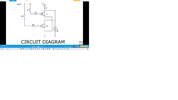
Why in the diagram that attached ;the led is not on
when S-1 or S-2 is on .
some of the voltage from the Vcc could fall on 1k resistor and the other voltage (9 volt battery) could fall on the led and
should turn it on.
2 filles attached.
thank you
 

Attachments

  • NOR GATE1.jpg
    NOR GATE1.jpg
    270.1 KB · Views: 302
  • NOR GATE2.jpg
    NOR GATE2.jpg
    396.7 KB · Views: 291
If either transistor is on, the lower end of the resistor is pulled down to near 0V, so there is next to no voltage across the LED.

LEDs need a certain voltage before they emit any light; around 1.8V for red and progressively more for yellow, green and up to about 3V or so for blue.

Or to look at it another way, the LED is being shorted out by the transistor - the transistor takes all the current when on, so none passes through the LED.

In electronics logic terminology, it's an "Open collector" junction, where two or more different outputs (the transistor collectors in this case) can pull a point in the circuit low and the "high" is given by a resistor when no output is on.

 
Your gate is NOR. With OR any input that is high creates a logic "1" on its output,
read LED you would desire to be on. But its NOR, so OR output is inverted,
such that LED is off anytime an input goes to 1.

1652351324622.png


Regards, Dana.
 
Status
Not open for further replies.

Latest threads

New Articles From Microcontroller Tips

Back
Top