Continue to Site

Welcome to our site!

Electro Tech is an online community (with over 170,000 members) who enjoy talking about and building electronic circuits, projects and gadgets. To participate you need to register. Registration is free. Click here to register now.

  • Welcome to our site! Electro Tech is an online community (with over 170,000 members) who enjoy talking about and building electronic circuits, projects and gadgets. To participate you need to register. Registration is free. Click here to register now.

NOR Gate circuit - Can it be built with floating inputs

Status
Not open for further replies.

DamoRC

Member
Apologies for what might turn out to be an annoying question.

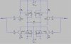
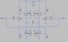
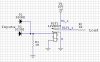
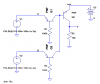
Is it possible to build a NOR gate with 2 inputs without having the inputs pulled high by default (i.e. have them "float")?

Can this be done with discrete components such as transistors, resistors, diodes, chicken wire and a couple of rubber bands (chicken wire and rubber bands optional).

In case I have defined the problem incorrectly, my understanding of a NOR gate is that the output is high only when both inputs are low.

I have looked at a number of NOR circuits (for example this one: **broken link removed**) but in all cases the inputs are pulled high by default.

Or is the concept of a NOR gate with 2 floating inputs irrational?

Thanks in advance.
 
I could be wrong, but this sounds like another case of describing the step instead of the goal. We get a lot of those here. Check out the entire document while you are there (scroll to the top).
Tell us why you are asking this question. It might turn out to be irrelevant to what you are trying to do (if anything). Or not.
 
Last edited:
What is the purpose of having them "float". Normally that's considered an undefined condition. You either should have digital inputs high or low (1 or 0). Otherwise the outputs are indeterminate.
 
What is the purpose of having them "float". Normally that's considered an undefined condition. You either should have digital inputs high or low (1 or 0). Otherwise the outputs are indeterminate.
Floating TTL inputs is fairly common, but is poor design practice. Floating CMOS inputs will definitely yield undefined outputs, and will frequently lead to high current draw.
 
If you build your own NOR gate and not rely on an existing logic family then you can define the two input states to be anything you want. But before you begin, realize that this is binary logic, so you must define two input states, not one, and not three or more.

Perhaps you could base the two states on source resistance driving the gate or a combination of voltage and resistance (ie. current). A discrete circuit may be the way to go to realize this gate. If you don't mind it having fairly low switching speed (compared to, say, 4000 series CMOS) it should not be difficult.
 
Last edited:
Ok here is my Rube Goldberg no pullup NOR gate. Hope glitches are okay... lol
Yeah, I did not bother changing voltages to TTL. Lazy...
 

Attachments

  • Norgate.jpg
    Norgate.jpg
    34.9 KB · Views: 334
Last edited:
You can do it with PNPs. You may recognize it as the PNP version of the TTL NAND gate, with the logic levels inverted (0=high, 1=low). If you float an input, the result is the same as if the input were grounded.
 

Attachments

  • PNP NOR gate.PNG
    PNP NOR gate.PNG
    9.6 KB · Views: 465
  • PNP NOR gate.asc
    1.5 KB · Views: 138
Last edited:
Ok, yours is better, but where is the chicken wire? Mine had a rubber band for the relay :)
 
Ok, yours is better, but where is the chicken wire? Mine had a rubber band for the relay :)
I know, I was much too serious. I didn't get started on my design until I could get up off the floor after looking at yours.:D
 
As always thanks for the responses and ideas.

Mikebits, will the output of your "Rube Goldberg" NOR gate be high if both inputs are low?

To address Roff's concerns I will describe the project in more detail than I had originally intended to bore you with.

I am trying to build a circuit for a radio controlled car that allows me to supply 6 or7 volts to the stock electronics package but 12-15 volts to the motor. I cannot simply feed 15 volts to the stock electronics as they will fry. The original discussion of this project can be found on this forum here.

So the plan is to feed the stock electronics with a voltage regulator and take the pulses from the stock H-bridge, that were originally destined for the motor, and pass them to a circuit that would trigger a second H-Bridge capable of handling more power. The original circuit diagram is attached (Version 1)

The outputs from the stock H-Bridge are inputs to the circuit I am trying to build and are as follows (these are pulsed from float(?)):
A high, B low = forward
A low, B high = reverse
A low, B low = brake
A and B off (float) = coast.

The problem I came across was that in version 1, the PNP inverters (low side) were driving the input lines to these inverters high which triggered the input line to the NPN inverters that drive the high side. I set it up this way because I was thinking of the brake function (both low inputs would trigger both N-MOSFETs on the low side). I did not forsee the PNPs having high base states. So this circuit does not work.

I re-worked the circuit to what you see in version 2. This works just fine, forward, reverse and coast, and I am quite happy with it. However, I have no brake function. I thought that if I could come up with a NOR gate with floating inputs then when both inputs are driven low, I could independently trigger both low side N-MOSFETS via some sub-circuit. Thus my search for a NOR gate with floating (rather than high) inputs.

I hope this adequately decribes the goal rather than the step.

p.s. it took me so long to write this that both Mikebits and Roff have added more comments which I have not read yet. Also, please ignore the specific part numbers in the circuits, I just put these in in LTSPICE, they are not the parts I have used.
 

Attachments

  • H-Bridge Version 1.jpg
    H-Bridge Version 1.jpg
    75.8 KB · Views: 261
  • H-Bridge Version 2.jpg
    H-Bridge Version 2.jpg
    70.4 KB · Views: 332
Last edited:
Mikebits, will the output of your "Rube Goldberg" NOR gate be high if both inputs are low?
Yes, but don't use my circuit, I was just being a smart alec. Although you could use the diode OR part + resistor with an inverter. Floats would appear as no current, output would be high.
 
Last edited:
I know, I was much too serious. I didn't get started on my design until I could get up off the floor after looking at yours.:D

Were you laughing? My goal, make someone giggle or chuckle once in awhile :)
 
Sorry guys. Based on your responses I seem to have botched the question and this is probably because I have stated the step rather than the goal at the top of the thread, as Roff suggested.

If you would bear with me, let me try to re-state.

If you examine the Version 1 circuit that I have posted above you will see that to switch the low side N-MOSFETs I have used a PNP Inverter (low in -> high out). The inverter itself works fine independently but it causes havoc when combined (at INPUT A) with the NPN inverter on the same side of the bridge. Because the input to the PNP inverter is pulled high by default (awaiting a low to trigger it) it automatically triggers the NPN inverter. I guess what I am really after is an PNP type inverter (low in, high out) that does not require the input to be pulled high by default but rather lets it float.

Thoughts?
 
Would it be possible to change the fourth state to A=Hi, B=Hi, perhaps with some pullups on your stock H-bridge? These are defined states, and you should be able to handle them logically.
 
Thanks Roff but no can do. Firstly because the goal was to not interfere with the stock electronics making this a "plug and play" type add-on and secondly, and more importantly, because I would have no idea where to start on the stock electronics to achieve such a result.
For the time being I am going to solder up what I have. Might try again at a later time with a H-bridge driver.

Thanks again
The pullups could be added to the A and B inputs of your new circuit. Don't they connect directly to the outputs of the stock H-bridge?
 
The pullups could be added to the A and B inputs of your new circuit. Don't they connect directly to the outputs of the stock H-bridge?

Yes they do.

Pulling both inputs high as the default condition of the circuit would mean the coast condition would be two highs. Let me brood on this for a while to see if I could make that work. Thanks for the suggestion.
 
Yes they do.

Pulling both inputs high as the default condition of the circuit would mean the coast condition would be two highs. Let me brood on this for a while to see if I could make that work. Thanks for the suggestion.
If you do a truth table, you'll see that the logic is really simple. If you need help with the truth table, let us know.
 
When you say "truth table" do you mean:
A high B high - coast
A high B low - forward
A low B high - reverse
A low B low - brake
?
 
Status
Not open for further replies.

New Articles From Microcontroller Tips

Back
Top