therealciviczc
New Member
Complete rookie here. I know absolutely nothing about electronics, but I'm trying to learn as I go.
I'm trying to build an LED that replaces the buzzer on my Golf Cart. The problem is that everything on a golf cart is 36 volts, including the buzzer. I removed the buzzer and just left the leads disconnected, and everything works fine on the cart, but I can never tell when I'm in reverse, so I want an LED.
Here was my brilliant idea, feel free to frame this artwork...
**broken link removed**
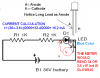
The volt meter is only there for testing. So before I hooked up the LED, I tested as the voltmeter shows, from the resistor to the negative, to see what voltage the LED would be seeing. To my surprise, it was still the full 36 volts. It didn't matter if I had the resistors in there or not, the volt meter still sees 36volts.
The resistors are 1kohm, 1 watt, 5%, and wired in a series.
Any sort of direction is a step forward because I'm clueless.
Thanks, and sorry to clutter up the forum with elementry questions.
I'm trying to build an LED that replaces the buzzer on my Golf Cart. The problem is that everything on a golf cart is 36 volts, including the buzzer. I removed the buzzer and just left the leads disconnected, and everything works fine on the cart, but I can never tell when I'm in reverse, so I want an LED.
Here was my brilliant idea, feel free to frame this artwork...
**broken link removed**
The volt meter is only there for testing. So before I hooked up the LED, I tested as the voltmeter shows, from the resistor to the negative, to see what voltage the LED would be seeing. To my surprise, it was still the full 36 volts. It didn't matter if I had the resistors in there or not, the volt meter still sees 36volts.
The resistors are 1kohm, 1 watt, 5%, and wired in a series.
Any sort of direction is a step forward because I'm clueless.
Thanks, and sorry to clutter up the forum with elementry questions.
")