Continue to Site

Welcome to our site!

Electro Tech is an online community (with over 170,000 members) who enjoy talking about and building electronic circuits, projects and gadgets. To participate you need to register. Registration is free. Click here to register now.

  • Welcome to our site! Electro Tech is an online community (with over 170,000 members) who enjoy talking about and building electronic circuits, projects and gadgets. To participate you need to register. Registration is free. Click here to register now.
Status
Not open for further replies.

vne147

Member
All,

I’m working a project in which I will need to control the output of a DC/DC converter using a microcontroller. I’m planning on using the LM27402 DC/DC Controller IC from TI. My application circuit will be very similar to the circuit taken from page 2 of the evaluation board datasheet and shown here:

schematic-png.100416


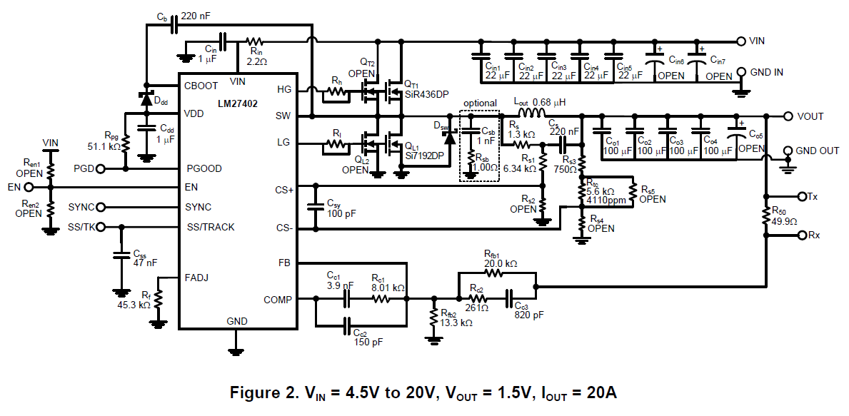
The datasheet very clearly explains how to vary the output voltage by changing the value of a single resistor identified as Rfb2. The equation that governs that relationship is in section 9.12 on page 9 of the datasheet and is:

[LATEX]R_{fb2}=\frac{R_{fb1}}{(\frac{V_{OUT}}{0.6}-1)}[/LATEX]

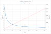
I want to vary the output voltage from around 1V to around 10V. So, I can easily calculate the range of resistances I’ll need to accomplish that task using the equation above. However, since I’m using a microcontroller, I’m thinking I’ll have to use a digital potentiometer in place of Rfb2. This would work, but my problem is that the above equation is nonlinear.

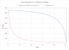
If I used an 8 bit digital potentiometer, I would only be on step number 128 (50% of full scale) by the time I used up 90% of my output voltage range. Here is a graph to show what I mean:

graph_1-png.100418


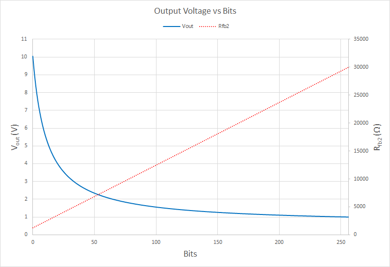
Since the digital potentiometer’s resistance varies linearly with its bit setting, the voltage output of the DC/DC converter will be non-linear with respect to the bit setting. This is unacceptable for my purposes. Basically, what I need is a way to vary the resistance non-linearly so that the output voltage is linear with respect to the bit setting. That is the change in output voltage is the same for each bit 1-2, 2-3, 3-4…255-256.

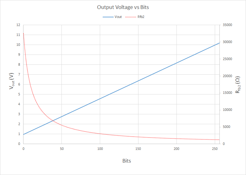
Is there some resistor network arrangement that someone can think of in which when I linearly vary the digital potentiometer, the resultant total resistance would be nonlinear? The general function I need the resistance to vary by is of the form:

[LATEX]R_{fb2}=\frac{\alpha}{(R_{POT}+\beta)}[/LATEX]
Where:

[LATEX]\alpha,\beta[/LATEX]
are constants.

Here is a graph of how I’d like it to work:

graph_2-png.100419


Thanks in advance for any help you can provide.
 

Attachments

  • Schematic.png
    Schematic.png
    62.9 KB · Views: 733
  • Graph_1.png
    Graph_1.png
    19.9 KB · Views: 893
  • Graph_2.png
    Graph_2.png
    21.5 KB · Views: 572
Last edited:
You can't change both Rfb1 and Rfb2 in a potentiometer arrangement since that will likely foul up the loop compensation.
My thought would be to connect the digital pot from the output voltage to ground and connect the wiper signal to the junction of Rfb1 and Cc3 to control the voltage.
The digital pot would need to be low impedance to not seriously affect the compensation (say 1k-2k pot).
If you need to use a higher value pot, then you could add a single-supply/rail-rail op amp follower (buffer) circuit between the pot wiper and Rfb1/Cc3.
 
I'm not planning on changing Rfb1. Only Rfb2.

If I replace Rfb2 with a pair of resistors in parallel (one a fixed value, and one a digital pot), then the resultant resistance varies non-linearly with the digital pot. However, the shape of the curve isn't what I need.

For your idea of adding a digital pot between Vout and the Rfb1/Cc3 junction, should I replace R50 with the digital pot, or place it in parallel?
 
Last edited:
Neither.
R50 is for loop response measurement purposes and can be left out, if you don't need it.
Otherwise connect in it series with the regulator output and the pot.
Note that the other pot resistor end goes to ground as shown below.
That way the wiper output should give you a linear voltage adjustment versus pot wiper position.
Note that the pot wiper at the top gives the minimum output voltage.

upload_2016-7-12_12-14-56.png
 
OK. Thanks for the clarification.

I'm not sure is I'll need R50 or not. I think I'll start out with using the digi-pot in lieu of R50 since it'll be easier to modify the evaluation board to do that. I'll be sure to connect the free terminal of the pot to ground. If that gives me trouble, I'll do exactly what your diagram shows.

A few follow up questions: you stated that with the pot wiper at the top position, that would yield the minimum output voltage. The way I see it, with the pot wiper at the top it's the approximate electrical equivalent of just shorting passed the pot and the circuit behaving as if it wasn't there at all. That leads me to believe that with the pot wiper at the top, the output voltage would be whatever is set by Rfb2 per the equation from my original post. Do you agree with that?

If so, that leads me to my next question: if I want to vary voltage between 1V and 10V, I should choose a value of Rfb2 that gives a 1V output. So with an Rfb2 that corresponds to 1V, and a pot wiper all the way at the top, the output of the circuit would be 1V. Then, if I want to go all the way up to 10V I would just adjust the digi-pot labeled as U3 in your diagram. Do you agree with that as well?
 
Hi vne147,
I think there is an error formula for Rfb2. I think the +1 on the bottom line should be -1.
Les.
 
Make sure that your digipot is rated for >10V.
 
Hi vne147,
I think there is an error formula for Rfb2. I think the +1 on the bottom line should be -1.
Les.

Les,

You're correct. That was a transposition error on my part. I went ahead and made the correction in my original post. Thanks for your sharp eyes and pointing it out.
 
Make sure that your digipot is rated for >10V.

Hmmm. A quick perusal through Mouser showed very few digi-pot options that are 10V tolerant and none of them were less than 5kΩ. I'm thinking I may need to use a buffer op amp as previously mentioned.

Crutschow, would you mind modifying your diagram to show me exactly how I'd implement that? After all, a picture is worth 1000 words. Thank you sir.
 
Hmmm. A quick perusal through Mouser showed very few digi-pot options that are 10V tolerant and none of them were less than 5kΩ. I'm thinking I may need to use a buffer op amp as previously mentioned..............
If you can find a 5kΩ, 10V tolerant pot, that would probably be acceptable since the maximum equivalent output impedance at the wiper (wiper at 50% position) is only 1.25kΩ (two 2.5kΩ resistors in parallel).
I would try that before I added the buffer amp.

Yes, you would adjust Rfb2 to give 1V output so that the pot in the upper position would also give 1V output voltage.
(You stated correctly how the pot works).
 
I haven't tried this yet, but I believe that you can control the output voltage by feeding a control voltage into the SS/TRACK pin.

See section 8.1.7 of the datasheet.
 
I think if you play with SS then:
>>The Under Voltage Protection will not work.
>>The Over Voltage Protection will not work.
>>The Power Good will not work.
>>The Hiccup thing may not work.
It is a good idea. You could set Vref to 0.3V or vary Vref from 0.2 to 0.6V. But this may cause unforeseen problems.

upload_2016-7-12_20-52-28.png
 
Some things. First, you can logarithmitize a linear pot by placing it in parallel with a fixed resistance. The combined parallel resistance will no longer be a linear function of the digipot code value.

Second, I suggest running through the design equations for a 10 V output (you don't state at what current). It very well might be that a single inductor value (and probably other component values as well) will not work for the entire desired output voltage/current range.

Third, converting a series resistance to an additional voltage divider in the feedback loop with a variable impedance, as in U3 in post #4, will significantly change the frequency and phase characteristics of the feedback network. If you go back to simply replacing Rfb2 with a digipot, and solving the linearity issues, you might have better results. It does solve the problem of voltage range across the digipot, thanks to Rfb1.,

ak
 
From a recent thread, we did not find part that could work over the supply voltage of the micro. There probably are some very old parts that can.

I was unable to find a part that would do that too. I'll have 12V on the board for other things. I was planning on using that as the supply for the digital pot and then just using a voltage level converter for the interface with the micro.

Some things. First, you can logarithmitize a linear pot by placing it in parallel with a fixed resistance. The combined parallel resistance will no longer be a linear function of the digipot code value.

You're correct. But as I stated in post #3, the resultant curve is not what I need it to be and I can't figure out what, if any, arrangement of fixed value/digi-pot there is that will give me the curve I need. That was my original question. Here's another graph showing what I mean:

graph_3-png.100459


Second, I suggest running through the design equations for a 10 V output (you don't state at what current). It very well might be that a single inductor value (and probably other component values as well) will not work for the entire desired output voltage/current range.

I'll need about 1V-10V at up to 25A. I understand the development board isn't designed to deliver that. I'm just using it as a starting point. A detailed process for sizing components is in the datasheet for the evaluation board. I'll be following that for the final design, but before I get there I still need to solve the linearity issue with respect to digi-pot setting. If I can't do that, I may have to start looking at alternate solutions.

That being said, does anyone have any ideas for an alternate solution that can output 1V-10V at up to 25A? No linear regulators here. I'm not looking to fry eggs.

Third, converting a series resistance to an additional voltage divider in the feedback loop with a variable impedance, as in U3 in post #4, will significantly change the frequency and phase characteristics of the feedback network.

I'm wondering about this also. But I think it's worth a little tinkering to see if the effects are significant in my application.
 

Attachments

  • Graph_3.png
    Graph_3.png
    20.6 KB · Views: 541
You're correct. But as I stated in post #3, the resultant curve is not what I need it to be and I can't figure out what, if any, arrangement of fixed value/digi-pot there is that will give me the curve I need. That was my original question. Here's another graph showing what I mean:.
In software or in hardware, invert the bits.

ak
 
8 digital outputs (0 through 255) > 8 inverters > digipot. 0 becomes 255, 1 becomes 254, etc. Plot that and see if it works for you.

ak
 
8 digital outputs (0 through 255) > 8 inverters > digipot. 0 becomes 255, 1 becomes 254, etc. Plot that and see if it works for you.

ak

The pot will interface with the microcontroller via a serial communication method such as SPI or I2C. It won't be a parallel data interface where hardware inverters for each bit can be used. That is unless I want to burn 8 I/O pins and add another data conversion IC between the micro and digi-pot, which I don't. Notwithstanding, what you're proposing can be easily accomplished in software, but unfortunately it doesn't create the curve that I need. I tried several different configurations before I posted this thread including the obvious solution of starting at 255 and counting down to 0.

When you count down instead of up, the only change to the curve in post #15 is that it gets horizontally flipped about a vertical axis centered at the 128 position.

What I need is a way to flip the curve vertically about a horizontal axis centered at about the 5.5V position. It sounds like there either isn't a way to do that, or no one, including myself, knows how.
 
Can you use a 256-position look-up table to correct for non-linearity?
 
Status
Not open for further replies.

Latest threads

New Articles From Microcontroller Tips

Back
Top