Continue to Site

Welcome to our site!

Electro Tech is an online community (with over 170,000 members) who enjoy talking about and building electronic circuits, projects and gadgets. To participate you need to register. Registration is free. Click here to register now.

  • Welcome to our site! Electro Tech is an online community (with over 170,000 members) who enjoy talking about and building electronic circuits, projects and gadgets. To participate you need to register. Registration is free. Click here to register now.

Noise reduction on HF amplifier

Status
Not open for further replies.

ok227

New Member
Hi everyone :)
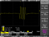
I'm trying to build HF amplifier for scintillator, but it's still catching some noise on oscilloscope (see pictures). Amplifier is mentioned for fast pulses. I tried put it to metal case to avoid inducted voltage, but it doesn't help. Does anybody have some idea what cam be wrong?
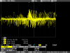
On photo you can see signal without noise which is there for most of the time, but on the second one you can see noise - I have no idea where it come from.
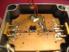
As amplifier Im using TQP3M (Qorvo company), circuit scheme is from their datasheet.

Thanks for your help :)
 

Attachments

  • SCRN0032.PNG
    SCRN0032.PNG
    18.5 KB · Views: 137
  • SCRN0038.PNG
    SCRN0038.PNG
    28.3 KB · Views: 141
  • Circuit_board.bmp
    569.8 KB · Views: 141
  • Scheme.bmp
    663.8 KB · Views: 126
  • IMG_5435.JPG
    IMG_5435.JPG
    992.6 KB · Views: 131
Im using TQP3M
Which version of TQP3M, there are many variations?
Can you provide a link to the datasheet?

I'm trying to build HF amplifier for scintillator
What is a "scintillator" ?
What kind of signal do you expect at the output of the scintillator?

JimB
 
Its the TPQ3M9008, I think.

That noise is definitely odd. It could be a circuit problem or a measurement problem.
If its a circuit problem, I would be suspicious of these things:
- DC power supply is unstable or noisy or faulty. Try with a battery to eliminate the possibility.
- the chosen amplifier has considerable gain up to 4GHz. Is it being intermittently unstable? What does a spectrum analyzer show about the output when this noise is occurring?

If its a measurement problem
- how are you attaching the scope ground?
- what are the scope settings? Filters?
- is the noise visible at the input as well as output? If so, then the amplifier may be fine but the signal source may be bad

Begin by addressing your measurement problems first.

I also want to mention that I'm not pleased with your soldering. It looks bad. Especially concerning is that the ground pins on the SMA connectors don't appear to be soldered to the PCB. They need to be soldered to the pcb. It also appears as if you need more heat from your iron.
 
Last edited:
+1 on the soldering criticism
Also: it looks like the two halves of the ground-plane are discontinuous until the SMAs are nailed down
 
In the absence of further information from the OP, I have made a few observations and assumptions.

The TQP3M9008 is specified for operation from 50 to 4000MHz. The input and output impedances are specified as 50 Ohm.

Looking at the oscilloscope traces, the wanted signal is a burst of 5MHz when measured in a 50 Ohm system.

Looking at the datasheet for the TQP3M9008, the coupling capacitors are specified as 1000pF for use at 50MHz.
A quick "back of fag packet" calculation shows that the reactance of the coupling capacitors will be 33Ohm at 5 MHz. A source of a few dB loss.
The reactance of the load inductor is about 10 Ohm at 5 MHz. Not high enough for a 50 Ohm system.

So, if the amplifier is set up as per the datasheet, the will be very little gain at 5MHz and plenty of gain at higher frequencies.

+2 on the soldering.
Clean off all that "gunk" (flux ?)
The connector at the input does not appear to be soldered to the groundplane.

The metal case is probably contributing very little (nothing ?) to screening from external noise in the current setup.


Suggestions:

Increase the value of the coupling capacitors and the load inductor by a factor of at least 10.
Add a low pass filter (10MHz cutoff ?) at the output, and maybe the input as well.
Clean up all the gunky flux on the PCB.

JimB
 
Status
Not open for further replies.

Latest threads

New Articles From Microcontroller Tips

Back
Top