Continue to Site

Welcome to our site!

Electro Tech is an online community (with over 170,000 members) who enjoy talking about and building electronic circuits, projects and gadgets. To participate you need to register. Registration is free. Click here to register now.

  • Welcome to our site! Electro Tech is an online community (with over 170,000 members) who enjoy talking about and building electronic circuits, projects and gadgets. To participate you need to register. Registration is free. Click here to register now.

Noise get into summing amplifier.

Status
Not open for further replies.

Minh Thanh

New Member
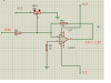
I am measuring EC of solution . I got Vec is 0.98V . After that, I took it to summing amplifier to reduce error from measurement . However, I saw a problem is that Vout of summing amplifier was continuously variable from 4.5V to 4.85V, not 1V - 1.85V with value of potentionmeter is 180k. I hope I receive your help . Tks you !
 

Attachments

  • Capture.PNG
    Capture.PNG
    21 KB · Views: 121
Last edited:
you could glance those papers that may have some setup ideas to your experiment (scroll to the bottom) AN13 , LT1011 , 1016 , **broken link removed** , 1671 ( , 1713 , 1716 )
as well as other typical functional block circuits
. . . you are using a MHz capable OPamps LF351 GBW 4MHz (previously/now) OPA07 600kHz
. . . if you don't have absolute precision biasing resistors and ideal op amps , and room PCB temperature control ... e.c. - in hand then you must experimentally (calibrate) tune your circuits into operation (preferably) re-calibrating* your meter prior/post any measurement , co*-logging your solution temperature (PCB temp* if later someone else should be able to rework/evaluate your sampling data statistically)

... there is no peak detector in your
s%C6%A0-%C4%90%E1%BB%92-m%E1%BA%A0ch-ec-png.107530
prev schem. so your output and should be more floating without ??
-------------- S T U P I D - T E S T -------------
Random_EEX_0100-a.png
 
Last edited:
just ticking it forward unless you spec next q.
found at the bottom of d/s some active DC sampling bridge balancer ??? i can't comment yet for what it's good for (PS! as with other d/s and this one contains notes about noise sources and some about avoiding such)
+
maybe http://www.slideserve.com/eamon/topic-12-op-amp-applications
you should boost it locally - your design
- take an agressive approach
- make a list of tasks solved (that "will do" for your setup)
- tasks needing improvement (as the one you posted here)
- make a more detailed notes about each solution in design
- preferably hand written on a paper (creates a better memorized / understood by yourself - a device-/device-status map)
. . .
random googling
http://en.wikipedia.org/wiki/Conductivity_(electrolytic)
http://en.wikipedia.org/wiki/Debye_length
**broken link removed**

you must eval. your design under a scope to track down the situation // sometimes for the OPamp with "sensitive input" a small cap from OUTP to InvINP will cancel oscillations / ringing sometimes the poor circuit layout is to blame if you use "direct coupled" , "feed back" stages the feedback may come from far forward from the sig.-path or through power rails (if the stages are not too stable or are not too stable by their inner nature)


LM318_ds.gif
(about LM318) found by tracking my comparators´ stuff
 
Last edited:
Status
Not open for further replies.

Latest threads

Back
Top