Continue to Site

Welcome to our site!

Electro Tech is an online community (with over 170,000 members) who enjoy talking about and building electronic circuits, projects and gadgets. To participate you need to register. Registration is free. Click here to register now.

  • Welcome to our site! Electro Tech is an online community (with over 170,000 members) who enjoy talking about and building electronic circuits, projects and gadgets. To participate you need to register. Registration is free. Click here to register now.

Noise generator humming.

Status
Not open for further replies.

Hero999

Banned
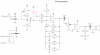
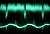
I'm building this noise generator to drown out my tinnitus but according to the scope waveform it appears to be picking up hum.

I know the TL082 doesn't have enough open loop gain at the middle of the audio bandwidth for a gain of 1001 but this is just a proof of concept circuit at the moment.

I assume, it's picking up hum because I built it on a breadboard and the long leads are picking up the mains. The interesting thing is it's only picking up the negative cycle at half the mains frequency. The power supply is my bipolar power supply which seems to be alright hum-wise.

Attached is the schematic and the waveform. The top waveform is the output from the noise generator and the bottom is the waveform generated when I hold the oscilloscope's probe and pick up hum.

I will build this on a propper PCB but before then, I want to ensure it works properly. Is there anything I might be doing wrong?
 

Attachments

  • Noise gen.gif
    Noise gen.gif
    8.7 KB · Views: 981
  • Noise gen and ripple.png
    Noise gen and ripple.png
    269.5 KB · Views: 1,010
Last edited:
Your zener diode is connected upside down. So instead of zenering and making a lot of noise, it is just an ordinary forward biased diode but with a lot of current. So that explains why the gain of the opamp must be so high.

Also,get rid of the breadboard and make the circuit properly.
 
You're right, the zener is upside down but it's only a schematical error, the zener in the real circuit, is the right way up. I've edited the attachment.

I suppose I'll have to build it properly before I can get it to work well.
 
hi hero,
I would be interested in how the tinnitus cancelling circuit works out.

I have tinnitus in both ears since the 1980's, when I damaged both of my ears working on a SMPS design.

The apparent frequency of my tinnitus is around 3 to 4kHz, low to medium loudness.

The specialists tell me there is nothing that can be done, except join a tinnitus group.

Regards
 
How did that happen?

Did a huge capacitor explode and take out your ear drums?

I got my tinnitus when I was about 15, I don't know, it just crept up on me. I had my hearing tested and they couldn't find any problems, except for a slight loss of sensitivity at the same frequency of the tinnitus, I was pressing the button saying I could hear the tone but it was jut the tinnitus, not the sound they were playing through the headphones.

It seems to be a problem with the nerves in my jaw, when I bite hard or push my jaw the tinnitus gets louder. I have a feeling that the nerves might have been damaged when I was involved in a fight and someone punched me in the jaw but I can't be certain.

The apparent frequency of my tinnitus is about 8kHz and varies quite widely in intensity, sometimes I can't sleep, but most of the time it isn't a problem.

The idea of this noise machine is to produce white noise to drown out the tinnitus, it sounds like a radio tuned out of station. I've tried leaving the radio on out of station before but it can suddenly randomly pick up a distant station which wakes me up. I've tried noise tapes but they have to be re-wound after so long.

I might add a low pass filter to output a pink noise as it's supposed to be less harsh sounding but at the moment I'll stick to white.

Currently I have this circuit set up in my bedroom with a piezo tranducer on the output, it produces enough noise to help me sleep and the piezo transducer doesn't have enough bass to reproduce the hum, so in a way it's fine as it is. When I finish the project, I'll add a speaker, an LM386 and split the amplification between two op-amps, I'll probably also add a pink noise filter which can be switched on and off.
 
Hero999 said:
How did that happen?

Did a huge capacitor explode and take out your ear drums?
hi,
I was working in a confined space tuning a SMPS, [24Vdc to 5Vdc] trying to maximise the efficiency. I accidentally detuned it to within the human audio frequency band. I heard two or three very load 'cracks', at first I thought it was the SMPS, but the crack was in my ears.

I have had a 3 to 4kHz tone ever since, Ive tried a number of ideas but with no success.

Normally I have learned to live with it, but sometimes an external audio frequency will 'beat' with it and then its very unpleasant.

As you say sometimes the 'tone' completely disappears for a few minutes, especially during the night, at which time I can hear ever little noise clearly.

You can buy endless loop cassette tapes for your tape player.

It would be interesting to see what other members have tinnitus and if they have found a 'fix'

The '**** Chat' topics may be the place to ask.
 
Asprin and Tylenol pain drugs cause tinnitus in some people.
I am an old geezer (62) but I still hear pretty well. I can hear up to about 15kHz. I heard ultrasonic motion detectors clearly when I was young.

I think I have a little tinnitus because I hear low level very high frequency noise (12kHz to over 20kHz) all the time but it doesn't bother me.
 
I've nearly finished designing the circuit.

I'm going to connect a small speaker so I've decided to move most of the gain to the LM386 because the op-amps dont't have enough bandwidth over the audio range.

The diode produces about 250:mu:V of noise which will be amplified by two op-amps, one with an optional filter selected by a switch to produce pink noise.

The circuit is pretty similar to the one below, except for the following:

  • The op-amps have a much lower gain.
  • They are both configured as single supply amiplifiers.
  • I've put a DC bias on the capacitors so they don't need to be non-polarised.
  • The noise source is a zener rather than a transistor.
**broken link removed**

I have a question regarding the LM386 circuit: what value coupleing capacitor should I use?

The datasheet says 250:mu:F but with an 8:eek:hm: speaker the lower cut-off frequency will be:

[latex]F_{C}= \frac{1}{2 \pi RC}= \frac{1}{2\pi 8 \times 250 \times 10^{-6}} = 80Hz[/latex]

I've worked out that for 20Hz I need a 1000:mu:F capacitor but is it really worth it as my cheap speaker will probably also roll-off at 80Hz.

Should I bother with 1000:mu:F or go for 470:mu:F which will give a roll-off of just over 40Hz and might be a good enough compromise?

Another question is, I'm tempted to go for a larger capacitor than 50:mu:F for the ripple by pass capacitor; is it worth it? I'm going to use unregulated supply and ams worried that a 47:mu:F capacitor at worst case might be only 37.6:mu:F (-20% tolerance) so it might not be good enough. I'm tempted to go for 68:mu:F or even 100:mu:F.

To be honest, I've never used an LM386 before and I want reasonable performance but I don't want to use too oversized components.
 

Attachments

  • Noise Gen1 - LM386.GIF
    Noise Gen1 - LM386.GIF
    6.9 KB · Views: 956
Last edited:
Use a high value output capacitor so the LM386 amplifier can damp the 100Hz to 200Hz boom sounds of the cheap speaker resonating.
You want wideband smooth noise, not a bongo drum.
 
I have your generic getting older tinnitus, I notice it in really quiet environments and have occasional loud ringing, somewhere around that 3-4k range. Getting more noticeble lately.
I did have an explosion incident when I was younger though =O. I unrolled and collected a dozen or so of those little novelty poppers (throw at the ground and they go off like caps) and wrapped them up in tissue to make a large one, loud as hell, it went so well I immediately and stupidly went to a dozen boxes of them. About six boxes in I noticed my face was getting warm and realized I was sitting in front of the heater vent in my room that had turned on. About 2 seconds later my mind went 'ding' (the stuff is thermally sensitive) and so did the bowl I was dumping the stuff into, more like a bang though. I had a mild powder burn to my face arms and neck (just a stinging sensation for a couple days) but I was stone cold deaf for a few hours and it took two weeks for the ringing to go away.
Live and learn I guess =) I think that was the first 'life' I lost =) I better keep count, I think I'm at least half way to 9 by now! I think 4 was nearly digging up the mains lines carrying 30-40KWs to the plant I work at (always ask your boss to see dig permits before your start working no matter how much you trust them!)
 
Last edited:
I know it's been a year, the project gotr put on the back burner.

I've managed to solve the hum problem.

Here's a picture of the waveform with the scope set to 5mV/div, one has the scale on and the other with the scale off.

There are no op-amps, just a 15V zener connected to a 1.5mA JugFET constant current source.

Do I have a perfect white nose waveform?

It's difficult to tell. I know the picture with the scale off appears to have a periodic waveform superimposed on the noise but it didn't change with the position or timebase was adjusted, I think it's the way the phosphor is applied to the CRT.

What's the amplitude?

Interestingly the blur seems to be brighter at lower amplitudes; does this imply that there's some pink noise mixed in or is it the attenuation of the cable? I didn't use a compensated ÷10 proble.

I suppose a scope isn't the ideal tool for this, I need a spectrum analyser.
 

Attachments

  • Scope Noise1.JPG
    Scope Noise1.JPG
    816.7 KB · Views: 494
  • Scope Noise2.JPG
    Scope Noise2.JPG
    426 KB · Views: 437
tinnitus

I have a fairly severe case from sleeping next to the diesel engines on board a conventional submarine in my early Navy years. I recently did a sleep study for sleep apnea and the lab have a white noise generator to help me sleep with all the leads and other contraptions, it worked quite well. It was a:
Amazon.com: marpac sleepmate - Health & Personal Care
:)
 
Those all look quite expensive, it looks like it's definitely worth building then.

audioguru,

The question is what should white noise look like on a scope?

At first I thought that it should be a solid bar of uniform intensity at the same amplitude as the nose.

I've realised that the waveform displayed on the scope will be brighter at lower voltages because of the scope's roll-off and the fact that I used an uncompensated lead didn't help.

Is that correct?

EDIT:
I want a minimum output power of 250mW RMS of output form the speaker.

That means the peak voltage across the 8Ω speaker should be 2V.

P = 2²/8 = 500mW

RMS power is half the peak power so this is 250mW RMS.

If the noise amplitude is 5mV, as you can se it's a bit more than that but never mind.

Therefore I need an amplifier with a gain of 400.

Is this correct or have I made any silly schoolboy errors?

This means I should be able to omit the second op-amp and use a single µA741 with a gain of two plus the LM386. The slew rate distortion of the LM386 shouldn't be a problem as its output will only be 10mV, the noise shouldn't be a problem since the whole purpose of the circuit is to create lots of noise.
 
Last edited:
The amplitude and frequency of noise is random. The peaks are as much as 10 times higher in level than the RMS level but you might not hear 5 times as sounding clipped. On a 'scope the center horizontal will be bright and become dimmer away from the center.

An LM386 with its gain set to 200 has a slew rate high enough to play higher than 20khz at full output. But its output power is probably too low. Try it.
 
I think I did this at college, I'm beginning to remember it now.

In theory, the noise should have infinite power at any voltage level because the bandwidth is infinite. In practice the bandwidth is limited to what we're interested in.

The question is, if I give a bandwidth, voltage and resistance, how do I calculate the power?

I've done a Google and most calculations seem to involve thermal noise.
https://www.electro-tech-online.com/custompdfs/2009/06/Noise_Tutorial.pdf
[latex]Vn_{(RMS)}=sqrt{Vn^2}[/latex]

I'm not sure if I fully understand.

Is n the bandwidth?

So if the peak voltage is 7mV over a 20kHz bandwidth, the equivalent noise voltage is:

[latex]Vn_{(RMS)}=sqrt{0.007 \times 20000^2}= 11kV[/latex], no that can't be right!

Another thing, I know pink noise has equal powers over any octave, so there's as much power from 20Hz to 40Hz as there is from 40Hz to 80Hz.

So the circuit needs to have a lower gain in white noise mode than it does in pink noise mode; I which to have two separate modes.

All I want to know is how do I calculate the gain for the pink and white noise settings?

I'll see if I can find my old college notes.:D
 
Here's the proposed final schematic.

One question: do I really need D4 (highlighted in red)?

I added it because I'm concerned a 15V transient, coupled by C3, might damage U1 or will R4 be enough to protect it?

U1 is a µA741.

U2 is an LM386.
 

Attachments

  • Noise final.PNG
    Noise final.PNG
    43.3 KB · Views: 456
here you go.... burn this wav-file (pink noise) to an audio cd and put it on auto-repeat :D

I had a car battery explode a foot away from my ear when I was welding an inner wing. (no replies are necessary containing the word "should" or similar)
 

Attachments

  • PINK.zip
    195.8 KB · Views: 318
do I really need D4 (highlighted in red)?

I added it because I'm concerned a 15V transient, coupled by C3, might damage U1 or will R4 be enough to protect it?

I'll willing to make a bet it be OK without, but you've got little to lose by leaving it in.

Nice circuit. Does R2 need AC bypassing?
 
Yes, a capacitor across R2 or R3 would be a good idea.
 
Status
Not open for further replies.

Latest threads

Back
Top