Continue to Site

Welcome to our site!

Electro Tech is an online community (with over 170,000 members) who enjoy talking about and building electronic circuits, projects and gadgets. To participate you need to register. Registration is free. Click here to register now.

  • Welcome to our site! Electro Tech is an online community (with over 170,000 members) who enjoy talking about and building electronic circuits, projects and gadgets. To participate you need to register. Registration is free. Click here to register now.

Nimh battery charger

Status
Not open for further replies.

MrDEB

Well-Known Member
Was going with Li-Ion but for safety going with Nimh but need a small footprint charger. Contemplating using a lm317 but how reliable is this type of charger. YES there are chips for a smart charger but implementing as pcboard space is limited.
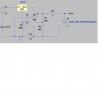
Found this schematic for a float charger but ??
any suggestions or comments concerning this schematic or similar. This is to be all smd but 1ohm resistors??
Trying to simulate so I have 3v on the battery which when fully charged is 4.8 but simulating a battery charger?
 

Attachments

  • 317 charger.jpg
    317 charger.jpg
    192.9 KB · Views: 367
Hello there,


This circuit doesnt look like it puts out enough voltage to charge four AAA cells. The NiMH cells will require about 1.6v each for charging, maybe a little less than that depending on the cell. That means at some point the charger has to be able to put out at least 1.6v, usually nearer to the end of the charge period. At that time the charge current should be lower too, like around 150ma even though 200ma is supposed to be OK. That's so you can leave it charge overnight without burning up the cells.

The max charging current of this charger is around 500ma, so that's not too bad, and the 1 ohm resistor allows a tapered charge as mentioned above but you'd have to test it to make sure it tapered correctly for your cells.

We can do a simulation.
 
Energizer and a Japanese Ni-MH cell manufacturers recommend NOT to trickle-charge at more than C/40 which is only 17.5mA for a 700mAh cell.
They recommend shutting off the charger when it detects a full charge.
MODERN Ni-MH cells hold a charge for 1 year so why bother trickle-charging them??

A Ni-MH cell is about 1.4V to 1.5V when fully charged and is fresh from the charger with no load so four will be 5.6V to 6.0V.
My new Ni-MH fully charged cells are 1.34V each after sitting with no load for 3 weeks.
 

Attachments

  • Ni-Cad and Ni-MH voltage.PNG
    Ni-Cad and Ni-MH voltage.PNG
    25.8 KB · Views: 234
Hi,

USB puts out 5 volts. You need a bit more than that to properly charge four cells in series. So you'd have to do two at a time, or build two chargers to do four cells at the same time. I cant recommend this however, i would recommend using a small wall wart.

Just to note, you can calculate your required source voltage and required series resistance for a tapered charge as follows:

The three equations are:

R=N*(Vbegin-Vend)/(Iend-Ibegin), and
Vs=Vend*N+Iend*R
Pr=2*Ibegin^2*R

where
R is the required series resistance,
Vs is the required DC source voltage,
Vbegin is the beginning cell voltage,
Vend is the ending cell voltage,
Ibegin is the beginning charge current,
Iend is the ending charge current,
Pr is the power of the resistor R.

For example:
Vbegin=1.0 volts
Vend=1.55 volts
Ibegin=0.500 amps
Iend=0.150 amps
N=4 for four cells

Using those parameters we would get:
R=6.2857 ohms
Vs=7.1429 volts
Pr=2*0.5^2*6.3=3.15 watts

So we'd set up the regulator to put out 7.14 volts and use a series resistance of around 6.3 ohms. The required resistor power rating is about 3 watts.
 
Last edited:
Thanks MrAl
One possible issue is the 3w resistor. available in smd ? and room in enclosure? as well as heat. The enclosure is basically a sealed enclosure where the user inserts a wall cube plug into side of enclosure. Would really rather use a rechargeable button cell but then we get back to li-ion batteries which I would rather avoid. Presently have 4 - AAA batteries in series each cell is 1000mah rating. With pcboard I have very little room. With the last link I realize I need more voltage input than the USB outputs. I simulated in TINA and circuit seems to work. BUT the large resistor and heat??
 
A simple resistor instead of a charger circuit will seriously over-charge a Ni-MH battery and will probably destroy it if it is not disconnected when it is fully charged. But how do you know it is fully charged??

I have a cheap charger that came with four AA Ni-MH cells. The charger is stupid because it does not detect that a battery is already charged and it does not detect that the battery is fully charged, it is simply a timer.
I don't know if a battery is completely discharged or is only a little discharged. If I charge one that is only a little discharged then the timer over-charges it very badly and it gets very hot which shortens the life of the battery. If the electrical power fails for a few seconds during a thunder storm then the stupid timer starts timing again and nearly melts the battery.
I heard some noises from the charger sometimes which might be the over-charging battery venting its chemicals.
 
This charger circuit measures temperature then goes to trickle charge which is supposed to be ok to use.
http://www.stefanv.com/electronics/usb_charger.html
I simulated this circuit in TINA using a TIP32 as well as a PMOSFET. seems to work. Thinking that to get a better handle on this circuit is to build it. I have the PMOSFET but need the lm393 but I have similar somewhere in my parts.
Have several NiMh batteries as well. If you see smoke rising from S.E. Idaho you know I got something wrong. lol
 
Hello again,


Well, if you cant use a 3 watt resistor then perhaps you can parallel several resistors. Otherwise you'll have to lower the current or use a more complex circuit.

To lower the current to 160ma to start and 50ma to end you can use a 20 ohm, 1 watt resistor, and a 7.2v voltage source (regulated by LM317 most likely).
It will just charge slower.
 
Not too concerned about length of charge.
Looking over the linked schematic and parts list I see no reference to any large resistors (MY bad I was still stuck on the first schematic I posted w/ large wattage resistors.
this schematic and explanation sounds good but hopefully can get in into a small enclosure.http://www.stefanv.com/electronics/usb_charger.html

The linked circuit charges 2 - AA 2500mah batteries in 5 hours but instead of 2500mah batteries I am planning on 4 1000mah AAA batteries so I need to calculate desired charging current.
Back to the drawing board but using a PMOSFET I hope I have no issues with heat as the linked circuit has?
 
plan is to charge at C/10 or below (10% of the rated capacity per hour). So a 1000 mAH battery would be charged at 100 mA for 15 hours or 200ma for 7 hours.
 
Straight from the horse's mouth:
Duracell's Manual: A number of applications require the use of batteries which are maintained in a fully-charged state. This is accomplished by trickle charging at a rate that will replace the loss in capacity due to self-discharge. In these applications, a trickle charge at a C/300 rate is recommended.

Energizer's Manual: Finally a maintenance (or trickle) charge rate of less than 0.025C (C/40) is recommended. The use of very small trickle charges is preferred to reduce the negative effects of overcharging.

So yes C/10 is not recommended for trickle charging; but saying that trickle charging is just plain wrong is not a true statement. Is it recommended; no it's not - but not because it is not safe. It is not recommended because statistically the battery manufacturer cannot guarantee the advertised battery life. This is a risk the battery manufacturers are just not willing to take. But they will acknowledge the need for trickle charging in some particular applications (as their manuals state), and they will even work with you to provide some life number, if trickle charging is unavoidable. To get these however, you must have NDAs in place with them. But please do not just state plainly that trickle charging is not an option.

A different version of a trickle charger with some smarts: https://www.electro-tech-online.com/custompdfs/2013/03/01463A.pdf
 
Duracell and Energizer have Ni-MH cells that hold their charge much longer than before, 1 year. Their manuals do not mention it so maybe the trickle-charge rate for the new ones is different than for the old ones.
I didn't look at Sanyo to see if their manual is updated.
 
WOW! the info makes for great reading but then I find this **broken link removed**.
A completely different opinion.
This charging circuit http://www.stefanv.com/electronics/usb_charger.html does both, a fast charge then a slow charge. My plan is to build circuit after I locate the thermistor somewhere in my parts mess unless my local RS has one in stock (the local store has lots of outdated stuff). Instead of using the TIP32 I plan to use a MOSFET but if I read the circuit explanation right the TIP32 only carries 470ma so maybe a simple pnp transistor but kinda iffy. I simulated in TINA using both the TIP32 and a PMOSFET. Very similar results but with less loss (HEAT) using the PMOSFET IMO.Need to locate a wall cube with at least 8v. A LM317 comes into play.
 
Most P-channel Mosfets need 10V from gate to source to completely turn on. You do not have 10V.

A Mosfet produces exactly the same amount of heat as a transistor in a linear circuit like this because it is simply a controlled resistor.
 
The linked circuit mentions the transistor beta and the current limmiting resistor R5 which controls the charging current.
"Doug, R5 controls the Emitter-Base current of the transistor. This, multiplied by the transistor’s beta (current gain), control the Emitter-Collector current, which is what flows into the battery. Many introductory electronics texts not withstanding, a transistor is not a simple switch; it’s an analog current control."
going to rethink the use of transistor type.
 

Attachments

  • NDS356AP.pdf
    81.5 KB · Views: 266
Last edited:
circuit explaniation talks about beta

the author states that the transistor beta is what controls the charging current?
"Doug, R5 controls the Emitter-Base current of the transistor. This, multiplied by the transistor’s beta (current gain), control the Emitter-Collector current, which is what flows into the battery. Many introductory electronics texts not withstanding, a transistor is not a simple switch; it’s an analog current control."
I just need to build circuit. Got tyed up trying to get an RPI1031 tilt sensor working right.
 
Status
Not open for further replies.

New Articles From Microcontroller Tips

Back
Top