Continue to Site

Welcome to our site!

Electro Tech is an online community (with over 170,000 members) who enjoy talking about and building electronic circuits, projects and gadgets. To participate you need to register. Registration is free. Click here to register now.

  • Welcome to our site! Electro Tech is an online community (with over 170,000 members) who enjoy talking about and building electronic circuits, projects and gadgets. To participate you need to register. Registration is free. Click here to register now.

Newest twist.... DC-DC PSU decided to take extended lunch.

Status
Not open for further replies.

fastline

Member
Figured I would just start a different thread for this issue but is part of the Yaskawa VFD I am working on in my other thread. The VFD had been powering up normally without issue aside from the microcontroller output issue. Well, went to do some more circuit testing and the small PSU that runs the main PC board decided to take a break. Need a little help figuring this one out.

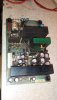
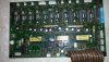
So... I have provided pics of the DC-DC PSU. this PSU receives 'unregulated' DC power from another board in which only a full bridge rectifier and capacitor reside. Why they did not just put this all in one PSU is beyond me! So the voltage going to the DC-DC board is 1.414* mains voltage or about 296VDC, but I measured right at 1VAC on those leads going to the supply. Is that acceptable ripple? I did not expect to see that much but its just a rectifier and cap feeding it.

If that is not the issue, I am a little lost because I expected to find a bad capacitor and so far all my ESR testing is showing things good right not.

So... Since I JUST tested that DC-DC board only 30min earlier, I know for a fact it was providing clean power. Voltages were reasonable and ripple was around 1mV. After it failed, I tested the rail for voltages and all were absent. I unplugged all load from the PSU and voltages came back a bit but still not right and reading low. Its like the PSU is straining over itself. I have seen it with bad caps in a SMPS but I cannot spot the issue here.

The big component on the sink by itself is a mosfet. I believe it is controlled by that daughter board as the switcher to bring the voltage down. I pulled the big cap hoping for an easy fix but it tests ok for now. I use ESR and a capacitance tester. I should probably up my game because I know some tests just don't show a bad cap. These caps are running north of 300V.
 

Attachments

  • 20181230_214725 MOD1.pdf
    1.1 MB · Views: 87
  • 20181230_220003 MOD1.pdf
    1 MB · Views: 94
  • 20181230_215927.jpg
    20181230_215927.jpg
    450.3 KB · Views: 87
The big cap is connected pretty much directly to the DC input, just the fuse, choke and NTC thermistor in line.
If the cap is not charging with DC input on the board it has to be one of those.

If it's been powered up too many times in quick succession the NTC may have cooked - or the fuse silently blown.


If it is charging, check R3 (ceramic near the power FET) and the three blue upright 33K & other upright resistors near them.

Also C8 and the other similar cap at the end of the choke. They look to be the PSUs own electronics supply for the JRC hybrid.
 
Well, I have been sort of back and forth with the power on it trying to solve problems. It was working fine BUT, as I mentioned, with no load on the converter, it appears to spit out "some" voltage so not completely dead, which is confusing me. Typically when I see that sort of thing, it is a capacitor.....

Any other dirty tests to prove that big charge cap is working? I did hit it with 18V and it handled that fine but it runs at 300V which might be a different story.
 
I checked everything you asked. All checks out fine I guess other than the NTC seems to check lower than I figured. It reads pretty much shorted right now and shop is cold, like 50F out there. It is a 10D-9. 10ohms at 25C. I am not getting that but....

Is the 1VAC of ripple going to the PSU at issue by chance? Maybe that NTC is doing something odd when under power?

Oh, the two caps, C8 and C9 tested good. I actually have brand new identical ones to test against and ESR was about .45ohms and capacitance with a DMM was on.
 
Is the big input cap charging to the same as the supply when it's powered up?

That info is needed to decide where to look next.

(And what is the voltage?)
 
Yes, the large cap on the PSU board in the pics is at full high voltage DC, which comes from another board as unregulated, rectified 208V 3ph. So it was around 296VDC.

The rectifier and another 220uf cap are on another board but just those two components.
 
Alrighty.... No replies but figured I would post an update. I made a quick bridge rectifier at home and used the same capacitor out of the other board that provides the rectified/unregulated DC to this PSU. I decided to swap C8 and C9 on the PSU. They are both 47uf/35V. The capacitors tests perfect capacitance with a DMM and ESR tested as new since I had identical new ones to install and test. I just decided since I already removed them for test, might as well replace.

I threw my 240V 1P power at the rectifier I made which made 350VDC to the PSU rather than the 300V it was getting. That should be in range for it since the VFD input voltage is rated for that.

The PSU fired up just fine and all voltages look very close. There is +5/+5/+15/-15/24/+5. All the 5s are 5.15V, 15 is 14.96, 24 is 23.78. I am just not sure how close these need to be but I know the 14V items that I know to use it would not care.

However, my concern is the AC ripple. Now, I do not have this thing grounded at all. But, when I tested this PSU in the machine originally, it was about 1-2mv of ripple. Now I am seeing 12mv on several channels and the last 5V was 30-40mv. The input side of the PSU has about 120mv of ripple, which I did test the PSU in the machine once it failed at about 1V.

I am just unsure how much ripple is usually acceptable and where the heck my problems even are with this PSU! I find lots of info on how and why to test ripple but not what is normal, acceptable, is a problem, etc.
 
Update, I decided I needed some load on that PSU to tell the story and it sure changed things. The two of the 5V took over 1A without issue and dropped to about 5.10V. The 15, 24, and the lonely 5V on the end were different.

The 15V at about .5A load dropped to 12V. 24V dropped like a brick. About .8A load it dropped to 8V, and the 5V on the end stopped outputting until I toggled the power.
The 15V had a very obvious flash or blink to it (driving a small light bulb) and you could hear the PSU trying.

The fuse on the PSU is 1.6A on the input and the min voltage the machine wants is 200V so that is 283V * 1.6A = 453W. I think the fusing is typically pretty close so as to blow if something is really wrong, plus most have some over current protection on the output.

Even so, assuming a measly 1A for each of the rails that is 3*5V*1A + 2*15V*1A + 1A*24V....That is only like 70W! Plus I was only loading one pin at a time. I just don't feel the PSU is up to snuff!

Any way to sort this or tell how much of each voltage I have here? My instinct is to just replace ALL the electrolytics on the entire PSU and start there.
 
Hi,
it's quite common on multi-output PSUs like that for main feedback / regulation to only be based on one output, probably the highest current one.

If that rail is unloaded when you measure another, the input power will not increase to match and you will get weird results.
It's most likely designed for all outputs to be loaded roughly in proportion, which would also keep them "in step" voltage wise.

The first 5V sounds to have held voltage, so that may be the main feedback source; see what the others do with your 1A load in that?
 
Ha, I talked to Yaskawa and they are a shade above zero help! they "don't have a print" for the PSU, don't know the voltages or currents, etc, BUT they can offer me repairs! lol SURE.....

rj, you are stretching my network of jumpers and meters! lol I get what you are saying. Still surprised the 15V was surging so bad though. That was the only voltage to do that and the last 5V completely dropped out.... Is that normal?

I am still baffled why this PSU went to sleep before, I replaced 2 caps around the driver, and it sort of works. If those caps were bad, I need to invest in better testing methods because ESR and std cap testing did not spot an issue.

Is there another way I can try to draw up some of the circuit to determine how this works for you? Knowing what the output should do would really help and I am going to call another repair center just to see if they will help.

I can tell you that 24V is probably well loaded as it serves to fire a decent sized contactor for soft charge directly. I am very surprised to see that! No diode or anything in that. I am sure it pulls close to 1A.

I know this PSU provides power to fire all the IGBTs so that could be the 5V. I realize the actual current needed could be quite low though as it doesn't take much and all circuits that use the 5V are just ICs, uCs, and such.

Also, am I barking up the wrong tree checking AC on the outputs? hovers around 60khz which is probably the switch frequency of the mosfet? Should that show up? This is not a "China budget" PSU, so I would expect high quality power from it.
 
I'd not worry too much about a bit of high frequency ripple at present. There is probably further decoupling at each rail on whatever it connects to.

The IGBT drive power is almost certainly separate from the general logic PSU, as the power side is "live" and each high side device needs its own drive voltage referenced to a phase output.
It's not unusual for there to be a high-frequency AC power source somewhere and separate miniature transformers and rectifiers for each output driver stage.
 
Ah! I think I understand. The front end mosfet driver is what will provide more 'gas' as needed BUT in some cases, mostly to cut costs, the front end is throttled while reading the current or demand on only one of the voltages as the current sense? In order to get truly isolated and modulated output for each voltage, you will need a fet and driver IC circuit for each voltage? I am certain I have another PSU that has this but it is WAY more complex. I think in Japan, they like these little daughter boards for each voltage driver. How you get that ceramic like stuff off to repair one is way beyond me!
 
This is really no help for the PSU stuff but may help in some clarity. This is the driver board for the IGBTs. The long line of plugs is where they go as well as some sensor inputs and such. For the PSU, 1P 210VAC is fed at CN30, ran through the bridge at D35 and C6 and kicked back out at CN31 as unregulated DC. 32-34CN receive unconditioned 24VAC from a separate small supply for "something". Maybe that is where they are making the power to drive the IGBTs? A coil for each phase perhaps?
 

Attachments

  • 20190102_104333.jpg
    20190102_104333.jpg
    1.3 MB · Views: 90
I suspect the lower half of that board is mostly another switched-mode PSU, with the single power device on the heatsink driving all three transformers, with four outputs each.

There are 12 output stages and 12 electrolytics with diodes between the transformers and the output sections.
 
Very very interesting! I try to take these opportunities to learn when I can. So, would it be prudent to at least 'assume' I may have solved an issue with the two caps replaced near the driver IC and I should reinstall this for testing in the drive? Should I go ahead and replace all the caps while it is out? I did accidentally leave the PSU powered all night and it was fine today, still showing the same voltage on all rails. I am a little concerned with the low 24V but maybe thats just as good as it gets? Possibly a resistor value was just a little wonky from the factory?
 
I'd give it a go and see what happens.

Have you tested the two startup resistors?
 
Update. I looked up the components on the heat sink. two are 15V regs, one is a 14V reg. The 15s are 2.2A max each, and the 24V is a measly 500mA. The mystery 4th I cannot find. Markings are SB100, 05, 5F2. You may be right that the whole thing is regulated with the 5V?

Also upon VERY close inspection, I can see micro cracks around a couple output pins. Not sure sure if that is a contributor yet but they will get reheated regardless. One of them is a ground pin. There are two that are traced up together but one is the lonely 5V that I lost output on so.....

Yes, I tested the soft start resistors. they both test perfect. I test fired the soft charge contactor with a 20V battery and ran continuity test through the circuit and both tested out at 10ohms so it should work if it gets switched. I am still unclear why it didn't fire before but now that I have a layout, I can test in the machine to find the issue pretty quick.

With the component data above and your input on how the front end mosfet may modulate, it is fair to say it may be ok.
 
Admitting my ignorance with some electronics, is this possibly the 5V that is being controlled with the front end? I would be interested to understand if I am even close by assuming the IC driver controlled the switching of the mosfet to the schottky, and the schottky runs in reverse acting as a rectifier for the high frequency? The other voltages seem to just have regulator ICs with limited current.

Sorry for the educational questions. SMPS still mystify me to this day and we have LOTS of them in the CNC world thus my large desire to understand them better.
 
Yep. I'd guess that the 5V is just rectified and used as a feedback control for overall voltage regulation.

It's an overall loop, the high voltage switch feeding the transformer, that to the rectifier and smoothing, then the DC voltage from there back through a feedback connection to control the duty cycle of the high voltage switch..

The other outputs presumably come from one or more extra secondaries on the transformer, via recs + caps, to the separate regulator ICs.
 
Status
Not open for further replies.

New Articles From Microcontroller Tips

Back
Top