Continue to Site

Welcome to our site!

Electro Tech is an online community (with over 170,000 members) who enjoy talking about and building electronic circuits, projects and gadgets. To participate you need to register. Registration is free. Click here to register now.

  • Welcome to our site! Electro Tech is an online community (with over 170,000 members) who enjoy talking about and building electronic circuits, projects and gadgets. To participate you need to register. Registration is free. Click here to register now.

*Newbie* Multisim 8 PIC LED Simulation

Status
Not open for further replies.

Deadwood

New Member
I'm trying to simulate a led circuit using a PIC12C508 (random choice).
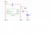
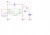
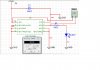
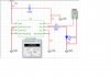
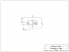
Here's a picture of what I have but how do I set the output to high without a program for the microcontroller in Multisim. I get close to 1V from GP0 but need at least 2.4V. I've thought of adding a spdt from source to GP3 and ground but that doesn't work. Just wondering how to control the microcontroller in Multisim 8.
By the way, should I look at getting Multisim version 10 for MCU function?

I'm very new to the practical part of electronics and have ordered both of David Cooks books so understand if I'm very lost.
 

Attachments

  • 1.jpg
    1.jpg
    72.5 KB · Views: 2,759
  • 2.jpg
    2.jpg
    73.5 KB · Views: 1,234
3 things to check:

#1. How much current can your supply output?
#2. What is the current limit on the output of GP0 ?
#3. Measure the voltage in 3 places:

1. Between Vdd and GND
2. Between GP0 and GND
3. Between the LED and GND

That will tell you alot about what is going on in the circuit.
 
I've checked in those spots but find I'm getting very little current at GP0. This is why I thought I have it wired wrong, am missing a control switch or am not using Multisim properly.
Here's a few volt measurements, one across PIC and the other across resistor and LED. I believe they should be the same but they are not. I also changed the resistor to 510 ohms...I was too high on the first circuit to trigger the LED.
 

Attachments

  • 3.jpg
    3.jpg
    96.5 KB · Views: 1,079
  • 4.jpg
    4.jpg
    91.4 KB · Views: 1,410
Why all the pins grounded That's not good You have the chip in reset by holding mclr
to ground. The chips not running
 
Last edited:
They're not suppose to be? I saw it somewhere and thought it was norm....I'm new here. :D
be80be...thanks for the reason why mclr shouldn't be grounded...explainations are great....but I'm still lost as to why my voltage and therefore amps drop after microcontroller.
 
Last edited:
Well it like this I bet your grounding your chip in your code but you didn't post that I would hook it up like this
 

Attachments

  • 508.png
    508.png
    6.2 KB · Views: 889
I haven't made a program code, just trying to simulate microcontrollers in Multisim. I'm wondering if I need to make a program for the microcontroller and run it in Multisim....is that how one controls the simulated microcontroller?
I understand that Multisim version 10 has a MCU function that allows one to run their code in a circuit inside Multisim.
 
How it going to do any thing you program it and run it. The program what makes the pins
input output high or low Like this It was for a 12f508 but it will work on your chip
Code:
	list      p=12C508            ; list directive to define processor
	#include <p12C508.inc>        ; processor specific variable definitions

	__CONFIG   _MCLRE_ON & _CP_OFF & _WDT_OFF & _IntRC_OSC


;***** VARIABLE DEFINITIONS
temp	EQU     0x07        ;example variable definition


;**********************************************************************
	ORG     0x1FF             ; processor reset vector

; Internal RC calibration value is placed at location 0x1FF by Microchip
; as a movlw k, where the k is a literal value.

	ORG     0x000             ; coding begins here
	movwf   OSCCAL            ; update register with factory cal value 


start
		
	nop 			  ; example code	
	movlw	0x00
	tris	GPIO               ;sets all pins to out put       
	movlw   0xFF              ; makes them high
	movwf   GPIO              ; leds on 


	END                       ; directive 'end of program'
 
Last edited:
Are you saying I can input a program like this into Multisim?

Or are you referring to real world simulation here....cause I'd like to simulate microcontrollers in Multisim first.
 
It ill be something like that. It has to be code that will run on the chip and the sim I have used use assemble like that.
 
Multisim can run code that you make with Hi-tech C I tried it out I do not like it I use this
 

Attachments

  • ISIS.PNG
    ISIS.PNG
    81 KB · Views: 1,223
Last edited:
Okay, I guess I'll have to look deeper into Multisim to find out how to simulate a microcontroller with program code....I need more practice. It's funny cause I'm having a hard time simulating a microcontroller when I've been able to do the same in real world on a BasicX-24. It's a learning process that will pay off.

Thanks for your help be80be :D ....a push in the right direction....Where in Multisim do I find the function to insert program code?
 
For others looking for the same function in Multisim, I found this link...it refers to Multisim V10.

The MCU functionality in Multisim enables students, educators and professional users to program MCU's in assembly
or C language within the familiar Multisim environment. The MCU capability can be used with any of Multisim’s
virtual instruments for a complete system simulation, including the microcontroller and all connected analog and digital
SPICE components.

ftp://ftp.ni.com/pub/devzone/pdf/tut_5629.pdf

I've looked for this wizard in Multisim V8, but I don't see it there...need to upgrade I guess.
 
be80be....thanks for showing me Labcenter's Proteus...I've read up on the software and find it supports microcontrollers that I have and will be using.
I'm making the switch to Proteus 7.4...now it's a matter of learning this new software.
 
Status
Not open for further replies.

Latest threads

New Articles From Microcontroller Tips

Back
Top