Electro Tech is an online community (with over 170,000 members) who enjoy talking about and building electronic circuits, projects and gadgets. To participate you need to register. Registration is free. Click here to register now.
Welcome to our site! Electro Tech is an online community (with over 170,000 members) who enjoy talking about and building electronic circuits, projects and gadgets. To participate you need to register. Registration is free. Click here to register now.
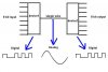
This is exactly the same as you're asking in your other thread, the devices are UART's (as before), and the easiest (and cheapest) way is probably to use PIC's to make them.
Yes, but why would you want to do that? (As depicted in your diagram) It would be better to use the PICs built in USART.
Most PICs have an ADC built in, but you'll need a DAC or use the PICs PWM and a Low Pass filter to go from digital to analog.
This site uses cookies to help personalise content, tailor your experience and to keep you logged in if you register.
By continuing to use this site, you are consenting to our use of cookies.