Continue to Site

Welcome to our site!

Electro Tech is an online community (with over 170,000 members) who enjoy talking about and building electronic circuits, projects and gadgets. To participate you need to register. Registration is free. Click here to register now.

  • Welcome to our site! Electro Tech is an online community (with over 170,000 members) who enjoy talking about and building electronic circuits, projects and gadgets. To participate you need to register. Registration is free. Click here to register now.

new to Ardunio but trying to compile

Status
Not open for further replies.
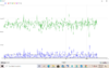
using the post #177 found PINK NOISE on youtube, adjusted the gain I think to lowest level.
I recall seeing somewhere that using 3.3v instead of 5v would reduce noise level. Might try this?
Code:
[code]

const int SoundIn = A0;
//const int Level;

void setup() {
  // put your setup code here, to run once:

  Serial.begin(9600);
}


void loop() {
  // put your main code here, to run repeatedly:

  int ADCValue = (analogRead(SoundIn)) ;          //this line reads the ADC input into the variable ADCValue

  int dBValue = 20 * log10(ADCValue);
  int Level = abs(ADCValue-512);
  //this line calculates the dB level of ADCValue and puts it in the varialbe dBValue

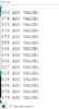
  Serial.print("ADC count: ");                                //this line, with the "print" command prints the label "ADC count: " and leaves the cursor at the end of the line
  Serial.print(ADCValue);                                     //this line prints the value of ADCValue where the last line left off and leaves the cursor at the end of the line
  Serial.print("     dB level: ");                               //this line prints the label "    dB level: " and leaves the cursor at the end of the line
  Serial.println(dBValue);                                     //this line, withe the "println" command prints the value of dBValue at the end of the line, and moves the cursor to
  Serial.print(Level);
  Serial.println(" level = ");
  //the beginning of the next line for the next measurement

  delay(100);                                                        //this line delays for 0.1 second before the process repeats
}
[/CODE]
 

Attachments

  • Screenshot (19).png
    Screenshot (19).png
    123.2 KB · Views: 279
  • Screenshot (20).png
    Screenshot (20).png
    200.9 KB · Views: 260
  • Screenshot (19).png
    Screenshot (19).png
    123.2 KB · Views: 267
  • Screenshot (20).png
    Screenshot (20).png
    200.9 KB · Views: 259
I know almost nothing about "C" programming but I don't see the logic of converting the actual ADC count to dB before converting it to w meaningful number.
THINK about what you are trying to do.

Les.
 
I did the screen shots BEFORE I saw your post.
I blanked out your suggestion and ran the plotter and get basically nothing.
I have something wrong, noting new.
will go get a morning coffee and get back at it later.
 
well I am back. I realized the heater fan was contributing to noise, here are the readings I took this morning.
NOTE I found the modules with the LM386 amp and considering disconnecting the mic for absolute silence?
these readings are in line with a reading of 512.
Got an email this morning about a module that appears very accurate for low level measurements ADS1115ADS
How to use the ADS1115
 
That's nice.

Perhaps when you learn to follow a logical sequence of steps and not abandon progress every time you encounter the least bit of trouble, someone will be willing to help.
 
experience.jpg

Dave Jones of the EEVBlog often mentions how lucky you are when a circuit you're building or code you are writing doesn't work as expected. Why? Because this is your chance to dig into the problem and do some troubleshooting to understand the problem and correct it. It's your opportunity to learn. If you encounter a similar problem in the future, you have a head start on solving it.


Sadly, MrDEB, your approach to troubleshooting isn't to roll up your sleeves and dig into the problem to figure out what's wrong and how to correct it. Your approach is to abandon what you're doing and search out another "code" to copy, or maybe a different piece of hardware to use, without ever understanding the problem in the first place. This entirely short circuits what Randy Pausch and Dave Jones have said.

Before anyone takes offense at this or argues about it, look back through the 10 pages of this thread (or any other MrDEB thread for that matter), and see how many times "I found this new code. Maybe it will work better hopefully."

So far, seeing any meaningful results, once the hardware issue as found, are the result of me typing out the code with the three commands needed. But since seeing a wee bit of data that looks realistic, no progress has been made. Changing the gain pot which varies the level by a factor of 5 has resulted in the comment "it didn't change things much." But we don't know how this was tested, and we haven't seen any concrete examples. I suggested making 3 measurements with a high-level noise source to determine the range of levels coming from the ADC, and which direction the gain pot rotates. Literally 10 minutes of effort. But instead, MrDEB is off searching for different hardware. We have yet to see meaningful measurements from this hardware, yet MrDEB has determined that he needs more resolution from additional hardware he won't understand.


I'll get off my soap box now. This is nothing new and I shouldn't be surprised. It's incredibly frustrating to attempt to explain things, and know the effort is for naught. Until and unless some meaning measurements are made, there's nothing more to be done here.
 
NOTE I found the modules with the LM386 amp and considering disconnecting the mic for absolute silence?
Got an email this morning about a module that appears very accurate for low level measurements ADS1115ADS
The LM386 is a power amp, meant to drive a 4-32 ohm speaker.

The module you're using with the MAX4466 has almost the same gain range.

Buying a 16-bit ADC module likely isn't going to get you anywhere except an emptier wallet.
 
Plus, the module he has has gotten good reviews for handling the normal range of sounds.

It's a matter of understanding what you're trying to accomplish and sticking to it.
 
not going to abandoned anything. Forgot to attach a file of the screen shot from this morning with the heater OFF
Question, if 512 is the mid point why not subtract 512 from measurements then any noise will show a blip in the wave form plotter??
 

Attachments

  • Screenshot (21).png
    Screenshot (21).png
    129.3 KB · Views: 252
Question, if 512 is the mid point why not subtract 512 from measurements then any noise will show a blip in the wave form plotter??
If all the measurements were exactly 512 then the plotter would show a flat line, same as it would if they were all 0. You're looking to see how large the changes are more so than the actual number.

When you're trying to debug something the less code the better. Even if it's "simple" code it might not do what you think it does.
 
I was looking at AudioGuru's sound level meter... The point of led's flickering works well, but a general volume could just work from peaks..


The circuit must deliver dB's before the level meter..
 
Here are the readings using post#168 and edited as per #179
the gain is indicated as CW(1st file) & CCW(2nd file)
 

Attachments

  • Screenshot (27).png
    Screenshot (27).png
    44.1 KB · Views: 283
  • Screenshot (28).png
    Screenshot (28).png
    46 KB · Views: 266
Post #179 asked for 3 explicit tests, with a quiet room and with a high level noise source, with results plotted out.

I am finished until you provide the info I have requested.
 
...with results plotted out.

MrDEB -

You want to show the entire plots so you can get a picture of what the average data looks like.
When you show just a few of the individual ADC readings it's almost meaningless... a few readings don't tell you much.

You also need to say if it's in a quite room, noise on, etc.
 
You also need to say if it's in a quite room, noise on, etc.

We also need to see that we're actually able to see some difference between a quiet condition and a loud condition. Hence the reason for taking measurements next to a blender, vacuum cleaner or other loud source. A blender or vacuum is also a broadband noise source.
 
my bad. Will have to do it after the wife wakes up.
Should work with pink or white noise and adjusting the volume up and down as well as the gain
 
Status
Not open for further replies.

Latest threads

New Articles From Microcontroller Tips

Back
Top