hi folks
im trying to add a 2002 speedometer and tacho to my 1991 suzuki gsxr.
Im giving the thing a whole new loom, that wiil be much simplified, im fairly happy rewiring the bike ive got all the components and their all large and self explanatory.
From fellow suzuki enthusiasts ive got a fair idea of what pins, on the connector block from the speedo/tacho unit, do what. (check out oldskoolsuzuki.info...info/membersprojects, for some awesome bikes )
)
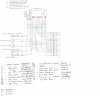
According to info from there, which im having trouble downsizing to attach, i need a "divide by two circuit" which takes a signal from a coil that pulses every time the piston is top dead centre, a "wasted spark". This division will give the tacho a true reading in rpm. From the research ive done it seems i need a D type flip flop gate blah blah blah, about now i start seeing gnomes and stuff, i dont think im capable of designing a workable circuit, do these chips need diodes and resistors and stuff what size etc?.
Again from the same source; the 12v feed into the instruments and into the /2circuit needs to have gone through a noise filter, i thought they went on phone lines. As a gizmo to regulate/maintain/manage frequency/bandwith i can imagine the need, but what do they look like how can i specify its parameters.
Can anyone here point me in the right direction, all info and wisdom greatley appreciated. Essentialy i dont know where to start, someone somewhere has done this before, can anyone here point me to a circuit diagram ?
im trying to add a 2002 speedometer and tacho to my 1991 suzuki gsxr.
Im giving the thing a whole new loom, that wiil be much simplified, im fairly happy rewiring the bike ive got all the components and their all large and self explanatory.
From fellow suzuki enthusiasts ive got a fair idea of what pins, on the connector block from the speedo/tacho unit, do what. (check out oldskoolsuzuki.info...info/membersprojects, for some awesome bikes
)According to info from there, which im having trouble downsizing to attach, i need a "divide by two circuit" which takes a signal from a coil that pulses every time the piston is top dead centre, a "wasted spark". This division will give the tacho a true reading in rpm. From the research ive done it seems i need a D type flip flop gate blah blah blah, about now i start seeing gnomes and stuff, i dont think im capable of designing a workable circuit, do these chips need diodes and resistors and stuff what size etc?.
Again from the same source; the 12v feed into the instruments and into the /2circuit needs to have gone through a noise filter, i thought they went on phone lines. As a gizmo to regulate/maintain/manage frequency/bandwith i can imagine the need, but what do they look like how can i specify its parameters.
Can anyone here point me in the right direction, all info and wisdom greatley appreciated. Essentialy i dont know where to start, someone somewhere has done this before, can anyone here point me to a circuit diagram ?

")
