Continue to Site

Welcome to our site!

Electro Tech is an online community (with over 170,000 members) who enjoy talking about and building electronic circuits, projects and gadgets. To participate you need to register. Registration is free. Click here to register now.

  • Welcome to our site! Electro Tech is an online community (with over 170,000 members) who enjoy talking about and building electronic circuits, projects and gadgets. To participate you need to register. Registration is free. Click here to register now.

New guy needs some help with schematic...

Status
Not open for further replies.

JSArcher

New Member
Guys, I need a bit of assistance....

I want to wire up an Auxiliary panel incorporated on the top clamp on my motorbike.

It's obviously 12v.

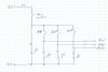
There are four push-button switches.
A master and three auxiliary, which I want to have the three working independantly of each other, but only when the master is on.

I want LED 'power indicator' which tell me when each is live.

Here's some pictures;

_MG_0003sml.jpg
_MG_0004sml.jpg

I can do all the fusing, and I know I need resistors for the led's, but can anyone help with how to best wire the main schematic?

Here's what I have so far;
Schematic - group.jpg


or with a fuse box; (please ignore the extra fuses)
Fuse box.jpg

I'm not (as you may have guessed) an electronics guru, so any ideas would be greatly appreciated.
Thanks in advance,

Jason.
 
Are you expecting the switches to carry the current for the auxilliary devices? If so, you need to make sure they are rated for the current levels expected - which would mean to the rating of the fuse being used.

If the switches are able to handle the current, then see attached s/d. Keep in mind though that the main switch has to be rated at a current level that includes all three auxiliary load currents.

If any of the loads exceed the rating on any of the switches, you can still use the same switch but you will have to incorporate a relay and the switch would just drive the coil of the relay.
 

Attachments

  • _0701092905_001.jpg
    _0701092905_001.jpg
    65.9 KB · Views: 204
Hey OuttoLunch..... thanks.

The switches say 125VAC on the back, but I now note that they appear to be 3A.

It says 2A.L / 3A (it's a Judco J188 push button)
_MG_0075tiny.jpg


I guess I'll have to use relays?

thanks again mate,

Jason.
 
Last edited:
for a GPS I would think you would be fine using just the switch. For the lamp - definately use a relay- as those switches are only 3A rated. The problem would be just keeping track of which switch has the relay and which ones don't - maybe easier to do them all as relays - if they can fit into your enclosure. Of course, if you protect the switch by using a 3A fuse or smaller, then you wouldn't have any worries by connecting a load that exceeds the switch's ratings. Use automotive relays - again making sure the current ratings are adequate.
 

Attachments

  • _0701113145_001.jpg
    _0701113145_001.jpg
    59.4 KB · Views: 203
Status
Not open for further replies.

Latest threads

New Articles From Microcontroller Tips

Back
Top