Continue to Site

Welcome to our site!

Electro Tech is an online community (with over 170,000 members) who enjoy talking about and building electronic circuits, projects and gadgets. To participate you need to register. Registration is free. Click here to register now.

  • Welcome to our site! Electro Tech is an online community (with over 170,000 members) who enjoy talking about and building electronic circuits, projects and gadgets. To participate you need to register. Registration is free. Click here to register now.

New driver circuit for 1W LED

Status
Not open for further replies.

zachtheterrible

Active Member
Yup, you heard right, I want to use the zxsc400 instead of the zxsc100. The main reason is that the current output only drops by .01amps when the battery goes from 3.3V to 1.8V! Can't say that for the zxsc100.
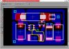
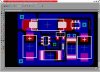
The other reason is that the component count is smaller and I was able to get all SMT parts for this circuit.

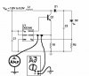
I'm having one problem with it though. It is the current sense resistor, R1, which is a 17milliohm resistor. This is what the datsheet says:
R1 is small and it is strongly advised to take track resistance into account. A proven method is to source a 1A current from the sense pin to the ground pin and check for 16-17mV. This resistor can be made from a 15 milliohm resistor with the track resistance contributing the difference.

I did exactly what it said and measured at the current sense pin. Problem is, I got 23mV, which means that my track resistance is too high.

I'm just wondering if I'm doing everything right? I have everything connected exactly as in the diagram. Ground is a piece wire sticking out from my board.

Also, how do I improve the conductivity? I have a layer of solder over the entire part of the circuit that is conducting the 1 amp.
 

Attachments

  • 23mv.jpg
    23mv.jpg
    26.2 KB · Views: 4,137
Hiya Zac,
Eh Mate I ended up getting that 1-3 watt led driver kit from Oatleys for only $9 OZ and I made everything as per da instructions but the most I got out of it was 3.6 volts @ 560mA with the pot turned fully on. They reckon it can handle both 1 and 3 watt led's but after I made both kits up they are the same. So in my opnion their only good for 1 watt led's and for $9 Oz it's cheaper to buy the kit rather than make ya own. As I'm in Oz if ya like I reckon I can get ya one and post em cheaper than their shipping price and I'm about to order some more stuff off Oatley's so it won't cost me any extra for a simple kit. Let me know if ya interested.

Cheers Bryan Very Happy

Hey Brian, looks like you posted in my double post before I could edit it to say that it's a double post, so I posted here instead :lol:

what kind of PSU do you use to power that driver kit? How big is the kit? (size is a large concern for me) and do you by chance know the efficiency?
Thanks for the recomendation :lol:
 
Hiya Zac,
Eh mate I'm off to da shed now to measure up the kit and get the spec's but eh man it's small bout 5/8'x 2-1/2" I reckon. But I'll be back in 10 dude :D
 
Hiya Zac,
Here's a pic of the kit, as usual silly me should of set up macro mode on me digi camera but the kit is just over 1/2" wide and 2-3/4" long and the high is around 3/4" due to to inductor and the cap. I reckon the inductor could be the reason I'm not getting the full amperage out of it as I just wound it by hand, guess I better make up that jig for the lathe for the next one. Anyway here's the link to the kit **broken link removed** and the 3 watt led is included mounted on the heatsink. I'm using a 12 volt 7 amp/hour battrey for the power supply but checkout the instrutions on the link for the power copsumption.

Cheers Bryan :D
 

Attachments

  • oatley_s_kit_and_3_watt_led.gif
    oatley_s_kit_and_3_watt_led.gif
    149.3 KB · Views: 1,834
Hi everyone again. I really need some help on this and I'm sure someone knows the math.

I have a 15 milliohm resistor and I need the track resistance to make up 2 milliohm to make 17 milliohms. If someone could give me the track area that I need in order to make this I would be greatful. Here is the info on the type of board that I have:
The copper on 1 ounce boards is 1.34mil thick (0.0341mm). This board is made of FR4 which is a flame retardant version of G-10 material. This flame retardant laminate is translucent in color and made of continuous woven glass cloth impregnated with epoxy resin.

Developed specifically for the circuit processing industries' requirements. Complies with Mil-S-13949H-GFK. Provides ultraviolet blocking and fluorescence when using automated optical inspection (AOI). UL# E37002A; 4/5/91

Provides high resolution and excellent fine line control. Ideal for prototypes, small production runs, and student training.
 
I get L/W = 3.948.
This comes from R=r*L/A where r=Cu resistivity=.6788e-6 ohms-inch, R=resistance (.002 ohms in this case), L=trace length, and A=trace cross-sectional area=W*t, where W is trace width and t is trace thickness (1.34 mils in this case).

**broken link removed** says the width should be at least 10 mils for 10 deg. C temperature rise. I think I would at least double that - maybe quadruple.
 
Ron I'm throughly confused with the result of this formula :lol:

Is 3.948 the length or the width or what? surface area?
:?

By the way, I have 3 more posts than you. Make that 4 :wink:
 
zachtheterrible said:
Ron I'm throughly confused with the result of this formula :lol:

Is 3.948 the length or the width or what? surface area?
:?

By the way, I have 3 more posts than you. Make that 4 :wink:
L/W=length divided by width. If you keep that ratio constant, you will get 2 milliohms (I hope), independent of the actual values. Since you will probably choose W to handle the current (I suggested 40 mils), then Length=3.948*40 mils =160 mils. If you make W=0.1 inch (100 mils), then L would be 0.4 inch.

1 mil=1/1000 inch.

I'm gonna have to increase my output. :wink:
 
Well that's a fly in the ointment. I don't have room for a 100 mil wide 400 mil long trace. Take a look at my layout. What's circled in yellow is the track that I need to be 2 milliohms. Maybe I'll just bite the bullet and hope it works with what I've got. I'll have to put some solder over it as well.

My last board didn't work because come to find out I had the transistor connected wrong. DUH!

I also might have the capacitors connected wrong. I assumed that the end with the stripe across it is negative polarity just like in through-hole capacitors. This whole board is SMT.

Two posts ahead of ya :wink:
 

Attachments

  • snapshot4.jpg
    snapshot4.jpg
    42.6 KB · Views: 1,449
Eh Zac,
Eh mate it's a shame you can't use 12 volts as the input source. I got the latest edition of siliconchip mag today and in the circuit notebook section is a 1 watt led driver circuit that won the monthly award. It looks pretty neat if ya wanna look just go to the silly chip website and take a look.

Cheers Bryan :D
 
zachtheterrible said:
Well that's a fly in the ointment. I don't have room for a 100 mil wide 400 mil long trace. Take a look at my layout. What's circled in yellow is the track that I need to be 2 milliohms. Maybe I'll just bite the bullet and hope it works with what I've got. I'll have to put some solder over it as well.

My last board didn't work because come to find out I had the transistor connected wrong. DUH!

I also might have the capacitors connected wrong. I assumed that the end with the stripe across it is negative polarity just like in through-hole capacitors. This whole board is SMT.

Two posts ahead of ya :wink:
You need to keep in mind that the current flows through the emitter of Q1 and through R1. It doesn't flow through the trace you circled.
Also, I didn't say it had to be 100 mils wide. Reread my post. 40 mils should be more than adequate. I reworked your layout to show you where the 2 milliohms needs to be.
 

Attachments

  • snapshot5.jpg
    snapshot5.jpg
    73.9 KB · Views: 951
If you make W=0.1 inch (100 mils), then L would be 0.4 inch.
But you said width .1 inch and length .4 inch :?

That was stupid of me, thanks for reworking that :lol:
 
zachtheterrible said:
If you make W=0.1 inch (100 mils), then L would be 0.4 inch.
But you said width .1 inch and length .4 inch :?

That was stupid of me, thanks for reworking that :lol:

From my first post:
This chart says the width should be at least 10 mils for 10 deg. C temperature rise. I think I would at least double that - maybe quadruple.
Note that 10 mils, quadrupled, is 40 mils (see next quote).

From my second post:
Since you will probably choose W to handle the current (I suggested 40 mils), then Length=3.948*40 mils =160 mils.
Also from my second post:
If you make W=0.1 inch (100 mils), then L would be 0.4 inch.
So yes, I said that, but it was just an example. What I was trying to emphasize is that the resistance will be 2 milliohms if you make the length 4 times the width. You can choose any width that will not burn up with one amp flowing through it.
And I had a heck of a time removing that danged yellow "circle" from your layout. :(
 
Ron, I've figured out the equation with these values for W and L:
W-.04
L-.16

I got R=.0124
Am I doing the equation right?

I don't get how you got the 1-4 ratio of width to length though?

I'm doin' my best here, please bare with me. It took me 20 minutes to try and get the equation right :lol:
 
Let's see if I can get the same answer twice. :roll:

R=r*L/A, and keeping in mind that A is cross-sectional area (not surface area),
A=W*t
so
R=r*L/(W*t)

solving for (L/W),
(L/W)=t*R/r

t=1.34*10^-3 for 1 oz copper,
r=0.6788*10^-6, resistivity of copper
R=2*10^-3 (2 milliohms)
so
(L/W)=1.34*10^-3*2*10^-3/0.6788*10^-6
(L/W)=3.948 I rounded it up to 4
**********************************
Checking,
R=(L/W)*r/t

R=4*0.6788*10^-6/1.34*10^-3
R=2.026*10^-3

which is darn close to 2 milliohms.

Don't mind me if I sound cranky. I'm old. :twisted:
 
Wanna see something funny?
Somebody who had no idea what they were doing made a linear driver.
Full of expensive heatsinks, fan, big non-adjustable power resistors to set the current. Wow, look how expensive doing it wrong is!
**broken link removed**
Read their description- OMG they use a TANTALUM capacitor! You guys are the best! Not those primative electrolytics that burn up after 1000 hrs.
I read the manual- they're really proud of themselves!

I ran into that product because the same seller has some acrylic Luxeon/Lamina covers, those may be useful.
**broken link removed**
 
Ron, thank you for your patience, I finally got the right answer. Part of the reason is that I've never really understood how to work with a scientific calculator and the: xxxxe-x. I stumbled through it, entered my track length and width and in the spirit of trial and error finally got the right sizes.
Can't say I understand the L/W equation, but I'll do that another time.

Oznog, that is laughable :lol: ! I wonder if that design is for driving multiple LEDs? Can't say I haven't done the same thing though, everytime I fire up my PSU to drive my LEDs :lol:

Aren't LEDs supposed to be indestructable? I would think that those covers would be more well suited for incandescent light bulbs :lol: By the way, I recognize the LED under the cover, but what kind of LED Is that to the right of it?
 
zachtheterrible said:
Aren't LEDs supposed to be indestructable? I would think that those covers would be more well suited for incandescent light bulbs
By the way, I recognize the LED under the cover, but what kind of LED Is that to the right of it?

LEDs indestructible? You've got a lot to learn Zach!
Luxeons usually stand off of a sink and are vulnerable to being knocked off or scratched. Lamina uses a silicone rubber lens that is not really tough. In either part you want to insulate the leads and keep moisture off them.

The one on the right is a Lamina BL-2000. Much more powerful that a Luxeon and they electrically insulated the thermal connection.
 
Well indestructable as compared to a lightbulb. I guess you're right oznog :lol:

How does that lamina LED differ from a standard 1W luxeon LED?
 
Status
Not open for further replies.

Latest threads

Back
Top