Continue to Site

Welcome to our site!

Electro Tech is an online community (with over 170,000 members) who enjoy talking about and building electronic circuits, projects and gadgets. To participate you need to register. Registration is free. Click here to register now.

  • Welcome to our site! Electro Tech is an online community (with over 170,000 members) who enjoy talking about and building electronic circuits, projects and gadgets. To participate you need to register. Registration is free. Click here to register now.

Negative V Regulator using Darlington

Status
Not open for further replies.

namtey

New Member
Hi

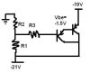
I am trying to regulate a negative voltage from about -21V to about -19V using a darlington transistor as shown in the figure. The darlington pair has a Beta of about 15000, and therefore with a desired Ic = 55mA, I calculate an Ib=3.76uA.

Can anybody advise a procedure for determining sensible values for the resistors in the voltage divider network on the base?

Thanks in advance.
 

Attachments

  • reg.JPG
    reg.JPG
    9.6 KB · Views: 179
Your circuit is not a voltage regulator.
Its output voltage will drop if the load current increases because Vbe will increase.
Its output voltage also changes a little when the temperature of the darlington changes.
Its output voltage also changes if the input voltage changes.

Three diodes in series will reduce 21V to 19V about the same as your circuit.
 
Thanks for your help.

Could you suggest what you think such a circuit would be used for? Somebody (who is not around right now!) suggested I use it in supplying the negative bias to the emitter in a Common-base buffer amplifier. I.e. the -19V will go to the emitter via a choke, and the -21V comes from a regulated supply.

THere is some ac decoupling between the voltage divider and the base to block any AC from making its way to the base of the darlington. (not shown in the crude pic)
 
I think that the intention is to provide isolation from a noisy power supply on the collector to the output on the emitter (using the isolation characteristics of the transistor (S12)).

Is this plausible?
 
The simple circuit passes supply noise through itself. If a capacitor is added at the voltage divider then it would reduce the noise.
 
Status
Not open for further replies.

Latest threads

New Articles From Microcontroller Tips

Back
Top