Continue to Site

Welcome to our site!

Electro Tech is an online community (with over 170,000 members) who enjoy talking about and building electronic circuits, projects and gadgets. To participate you need to register. Registration is free. Click here to register now.

  • Welcome to our site! Electro Tech is an online community (with over 170,000 members) who enjoy talking about and building electronic circuits, projects and gadgets. To participate you need to register. Registration is free. Click here to register now.

need your help

Status
Not open for further replies.

maxster03

New Member
Hi Everyone !

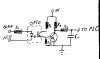
I am working on a project in which i have to connect a Smoke detector with a PIC16F877, i don't want the smoke detector buzzer to sound but i want it to send the input signal to the PIC when it detects smoke, i have tested the smoke detector and it is giving a 5V to -5V square wave, the sound buzzer has 3 wires red, black and white. i calculated the volatge across red and black wires.

Can someone tell me how I connect the smoke detector (which wire) with the PIC.

Thank you so much to everyone who replies in Advance

Murtaza
 
Use an optocoupler with resistor (turn it anyway you like, the internal diode will be on half the time if the voltage goes +5 - 5) on the coupler's other side you can place a capacitor to make sure the signal will stay high long, so that the PIC will have a logic 1 to read, whenever it checks (and a resistor in parallel with the cap so it won't stay high too long/forever).
 
First of all: I'm only a hobbyman, so my words are not to be taken as definite law.

Secondly: It is (as an effective rule of thumb) never a good idea to mix different power supplies.

But you can ofcourse try to just hook the two circuits up. If you do however two things should be kept in mind: 1: You can use the AD converter on the PIC (can't remember if the one you are using have an ADC, but some PICs do), then there should be no problem, but this needs additional coding. 2: even if you do that you need external components (a resistor network).
The easy, safe and secure way is really to use an optocoupler (since you have to use external components anyway it won't be that big a difference).

I have included a drawing (hand drawing sorry), that gives you a basic and easy/to/build circuit, that should work.

The principle is: When the black and red wire go active the optocoupler is activated (half the time) and the transistor conducts, this in turn pull the base of the normal NPN-ransistor to high and the transistor go on and pulls the capacitor to ground, the output to the pic is now low (output is high when no signal from smoke detector is available), the capacitor keeps the output low for some time (until the cap charges through R4, this is good because the pic will be quite fast compared to the audio signal from the buzzer. The +5 v supply to this circuit is of course the same as the one used by the PIC.

All resistors should be high value except the one driving the optocoupler, R5 should be much bigger than R2.

This circuit will only allow for very slow changes in state of the smoke detector, which I imagine is no problem.
 

Attachments

  • opto.jpg
    opto.jpg
    89.3 KB · Views: 132
Thanks alot,

I know this would seem a little foolish question but i just wanted to ask
shouldn't the RED and BLACK wire be opposite, because i think the Black wire should be where RED wire is and the RED wire should be where BLACK wire is :confused:

So your saying the input to the PIC would be HIGH when the smoke detector doesn't detect any smoke and would be LOW when it detects smoke ?

and it would be really grateful of you if you can just indicate the values of the RESISTORS so i can have a rough idea

Thank you really really much for your time and knowledge
 
If I’ve understood you correctly, then there is a square wave where polarity is shifting from red to black wire. that is: first current flow from black to red then from red to black. If this is so then it doesn't matter which way the wires are connected since it is an AC signal and not a DC signal. The Diode will be ON half the time no matter what way it is wired. There might be a different problem though: if you use a standard optocoupler like 4N25 it can only take 6v reverse voltage, since 5 volt is quite close to 6 I might include another small signal diode (any kind of diode really) in series after the coupler to cut the reverse.

When the diode is not turned on at all (no signal for the buzzer) no current will flow through the transistor on the other side of the optocoupler, which in turn means that there is no current flowing through the second transistor. This means that C1 is being pulled up (charged) to +5 volt, and the output is HIGH. HIGH = NO SMOKE

When the transistor turns ON (the buzzer would be on) the capacitor is being uncharged through R4 and the transistor and the output goes LOW. LOW = SMOKE

We want the charging to be slow (keeps the signal LOW for a long time and gives a lot of time for the microcontroller to read the port) but the uncharging should be fast.
Since the charging of a capacitor is determined by the formula Vc = V * (1 – e^(-T/R*C) and since we want to keep the voltage under 0,8 V (this is the upper limit for a logical Low for the PIC) for some time (say a couple of hundred ms). We could try for instance with a 100 mikrofarad capacitor and calculate a resistor value: 0,8 = 5V * (1-e^(-0,2 sec /R * 0,0001)) R=11K5 ohm, so R3 + R4 should be over 11k5, R4 should be small in order to make discharge quick, so you could try R4 = 560 ohm and R3 = 12k.
The rest of the resistors are more or less arbitrary: There should be about 10 mA on the diode, so try another 560 ohm for R1. R2 should let enough current pass for the transistor to be saturated good, try 1000 ohm. The pull down R5 should be much bigger than R2 but I don’t think it can be too big, so try 50k

Good luck
 
can you look at this diagram and tell me if tht is correct
i have also mentioned the Values.

Thanks :)
 

Attachments

  • New Bitmap Image.GIF
    New Bitmap Image.GIF
    33.6 KB · Views: 122
No, stick with Ove's original circuit. D9 makes it so your circuit won't work.
 
As Duffy said: The diode will make it impossible for the optocoupler to pull the base of second transistor all the way down to zero volt, the 50k resistor is also not needed in your design, however I understand that you want to invert the output, so it will be HIGH whe the smoke alarm is on. There is really no difference between a LOW and a HIGH when it comes to programming the PIC (its just BTFSS vs. BTFSC) - not any easier or harder. But you can invert the output, just have to recalculate the resistor values (now you need the cap to charge fast and to stay high a long time - with your/mine resistor values it charges slowly (bad) and goes low quickly (also bad)).
 
So what you guys are saying is tht i should remove the diode, keep the 50K resistor and the input to the micro controller would be high if smoke alarm is ON.

right ?
 
Loose the diode AND the resistor. Make R11 and R12 small so the cap charges quickly (with the current values it will never get the time to charge because the signal goes on and off all the time). You might get a problem making the ucontrolleer read the HIGH because the capacitor is less effective now, and you are running the risk of reading the port at a time when the cap is low although there is a signal from the smoke detector (when the optocoupler is off because current is being reversed between red and black wire).

try it on a breadboard!!!
 
can't i connect a full bridge rectifier, capacitor + resistor ... the works with a AC SINE wave, would tht work with a AC SQUARE wave
 
Yes. you can rectify a square wave as well as a sine wave with no practical difference, but what are you trying to do? The diode in the optocoupler allready rectifies.
 
i asked because with the full bridge rectifier i would only need one IC, but for the optocoupler i would need to make tht whole circuit, i think full bridge rectifier would be a better option :)
 
Why don't you trace out that smoke detector buzzer circuit back to the control chip? It should only take a few minutes, and will help us see what we're dealing with. Perhaps you only need a cap, resistor and a diode or two. Runs off a 9V battery, right?
 
Great. Big help. Engineers around the world applaud at the amount of effort you are putting into this. Try not to get too burned out from the sheer frenzied exertion.

Now trace that piezo circuit back.
 
Status
Not open for further replies.

Latest threads

New Articles From Microcontroller Tips

Back
Top