Continue to Site

Welcome to our site!

Electro Tech is an online community (with over 170,000 members) who enjoy talking about and building electronic circuits, projects and gadgets. To participate you need to register. Registration is free. Click here to register now.

  • Welcome to our site! Electro Tech is an online community (with over 170,000 members) who enjoy talking about and building electronic circuits, projects and gadgets. To participate you need to register. Registration is free. Click here to register now.

need someone to check for errors..

Status
Not open for further replies.

kpshamilsagar

New Member
hi all,
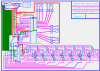
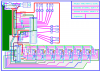
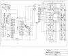
i am uploading the schematic of my project.i need someone to check for errors and need advice also....thanking you in advance..
 
Sorry - the schematic seems to be invisible and therefore hard to check !
 
i am sorry...forgot to upload...
 

Attachments

  • TRAFFIC22.JPG
    TRAFFIC22.JPG
    398.3 KB · Views: 192
The obvious error I can see is that SCK is connected to 5V. Look where they cross.

Mike.
 
The LED D2 [ power indicator] is reveresed.
 
those two corrected...any other errors?and how do i post a .pcb file here?

hi.
You could zip it.
What program was used to create the .pcb file.?

Use the Manage Attachments button lower down the Reply window
 
Last edited:
i have made the pcb by using expresspcb.check for errors in this also...

hi,
Checking the pcb artwork,, some errors are circled, correct it and repost.:)
 

Attachments

  • pcb2.png
    pcb2.png
    39.3 KB · Views: 170
Last edited:
i will be using some coating materials.u were talking about that cross only know.even i too got the same feeling then some of my friends told me that we can use the wire with plastic coating.so that problem wont come...
 
i will be using some coating materials.u were talking about that cross only know.even i too got the same feeling then some of my friends told me that we can use the wire with plastic coating.so that problem wont come...

OK, so you are using insulated wire links.?

Because you are switching LED's I would increase the value of C3 capacitor, what is its present value.?

Also add a 100nF decoupling capacitor close to the MCU on its power pins. pins 10 and 11
 
Last edited:
OK, so you are using insulated wire links.?

Because you are switching LED's I would increase the value of C3 capacitor, what is its present value.?
Also add a 100nF decoupling capacitor close to the MCU on its power pins. pins 10 and 11
yea i am using insulated wire..
value of c3 now is 100uf.should i change it?
i have put a capacitor between 10 and 11 of mcu.
i am not familier with max7219.is there anything else i will have to include on the max7219 part?please check that part and let me know...thank you...
 
Last edited:
yea i am using insulated wire..
value of c3 now is 100uf.should i change it?
i have put a capacitor between 10 and 11 of mcu.
i am not familier with max7219.is there anything else i will have to include on the max7219 part?please check that part and let me know...thank you...

hi,
I am looking at the datasheets.

The value of Iset for thr MAX7219 requires a resistor from +V to Iset.
Look at this image.

Checking all these points is going take some time, I will post again tomorrow.
 

Attachments

  • AAesp01.gif
    AAesp01.gif
    15.9 KB · Views: 155
hi,
It looks OK, I cannot check the LED's for pin accuracy as I dont have the type number, but segments are linked in order and so are the digit selects.

I would increase the 100uF to say 220uF also add some 100nF decoupling close to the LED power lines.

You should now recheck your artwork against the circuit diagram and datasheets.
I have carried out a careful check, but I will not be held responsible for any errors that may occur.
 

Attachments

  • pcb2.png
    pcb2.png
    41.8 KB · Views: 147
come on someone reply me about the atmega programmer..pls..

If you dont want to program from a PC, where are going to store the hex program.?

I have already given you links to atmega programming sources.?

ISP stands for In Circuit Programming
 
Status
Not open for further replies.

Latest threads

New Articles From Microcontroller Tips

Back
Top