Continue to Site

Welcome to our site!

Electro Tech is an online community (with over 170,000 members) who enjoy talking about and building electronic circuits, projects and gadgets. To participate you need to register. Registration is free. Click here to register now.

  • Welcome to our site! Electro Tech is an online community (with over 170,000 members) who enjoy talking about and building electronic circuits, projects and gadgets. To participate you need to register. Registration is free. Click here to register now.

Need some help with fast turn on/off Mosfet Circuit

Status
Not open for further replies.
Fast FETS

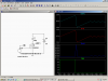
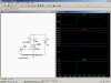
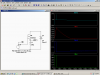
I haven't found a data sheet that looks like your part. On the surface it looks like it would work as long as you have pulses comming in. Most bootstrap drivers won't work for dc. I'm not sure what you mean by removing the MOSFET from harms way of any load. I think we are missing something here. If you are worried about the inductive "kick" at turn off that is what the diode is for. See the attachments. Note the very high voltage without the diode. In the other configuration the "body diode" of the FET "catches" the inductive kick (but not as good as the fast diode).
 

Attachments

  • ind1.PNG
    ind1.PNG
    46.3 KB · Views: 189
  • ind.PNG
    ind.PNG
    43.8 KB · Views: 177
  • ind2.PNG
    ind2.PNG
    44.3 KB · Views: 184
Ron, plot Vg-Vs in your last circuit. Remember that the max Vgs for most FETS is only ~20V. To reflect reality, you would have to float your input voltage source, and connect the + end to the gate, and - end to the source (Out)...
 
Last edited:
Yea, your right. I'm trying to figure out why he wants to put the load there.
 
Circuit would suplpy load with pulsed square waveform

I have found the circuit on the attached document page 19. I think that this circuit would allow me the flexibility of placing load on the source side of the Mosfet.
My concern centered around pin 5 of the driver and how the Voltage, Current and Frequency of the ouput in front of the inductor would affect it.
I like having the load on the source side as it removes Mosfet from the equation in terms of having to protect it.What ever tests I want to do in the future and what ever loads/frequencies do not have to worry aboutprotection of Mosfet. That is the main reason: want a flexible circuit. I wonder if this circuit would be ok if I just have the inductor as a load? Connecting output to a transformer?
 

Attachments

  • How to drive Mosfets and IGBT.pdf
    532.9 KB · Views: 346
I think you mean figure 6. Yes you could drive just an inductor, but remember the only thing that limits the current would be the impedance of the inductor. It would not work well for a transformer in the normal sense because it is a dc pulse.
 
Status
Not open for further replies.

Latest threads

New Articles From Microcontroller Tips

Back
Top