Continue to Site

Welcome to our site!

Electro Tech is an online community (with over 170,000 members) who enjoy talking about and building electronic circuits, projects and gadgets. To participate you need to register. Registration is free. Click here to register now.

  • Welcome to our site! Electro Tech is an online community (with over 170,000 members) who enjoy talking about and building electronic circuits, projects and gadgets. To participate you need to register. Registration is free. Click here to register now.

Need some help with fast turn on/off Mosfet Circuit

Status
Not open for further replies.

bmind

New Member
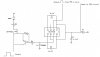
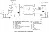
Would this circuit work? I am using a 555 timer to generate the frequency of need and then use a mosfet driver max4420 to drive the Mosfet.
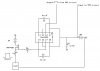
What would be an issue with this circuit.
Do I have to protect Mosfet against high voltage if I have an inductor on drain side or source side (between Rd and Mosfet) or against parasitic inductance?
I would like to keep IRFP running below 40C (may need heat sink). Any suggested max current/voltage limitation? Varaible resistor should accomplish the desired current for maximum efficiency.
What transistor would be adequate for this circuit?
How do we choose which Diode is best suited (I beleive this is dependent on driving current and 1N4148 can be used up to 150MA and BAS40 up to 300MA)
I was hoping to use this circuit as a frequency generator for various voltages/currents and wanted it to be fast turn on/off times hence the mosfet. Rd is only there to control current and is not the load.
I am newbie in electronics and am trying to learn. Any advice is appreciated.
 

Attachments

  • Fast turn on-off mosfet circuit.jpg
    Fast turn on-off mosfet circuit.jpg
    98.5 KB · Views: 884
Here is how I would do it:

The NE/LM555 can source/sink 200mA, so no gate driver is necessary. Put the load in the drain of the NFET. The 10K gate resistor is there only if pin 3 of the 555 gets disconnected from the FET. Don't forget to bypass the 555 rail.
 

Attachments

  • DF58.png
    DF58.png
    18.9 KB · Views: 1,130
Last edited:
Here is how I would do it:

The NE/LM555 can source/sink 200mA, so no gate driver is necessary. Put the load in the drain of the NFET. The 10K gate resistor is there only if pin 3 of the 555 gets disconnected from the FET. Don't forget to bypass the 555 rail.
Thank you for you help. I understand where the problem lies now. Would 555 timer be able to achieve fast turn on/off rate? That was the reason for the mosfet driver...would the driver inprove the turn on/off rate?
 
Thank you for you help. I understand where the problem lies now. Would 555 timer be able to achieve fast turn on/off rate? That was the reason for the mosfet driver...would the driver inprove the turn on/off rate?

There are gate drivers that can source/sink > 1A. The 555 sources/sinks ~0.2A. All things being equal, a 1A driver can charge/discharge the gate 5 times faster than a 0.2A driver. Is a 0.2A driver fast enough? Only you can answer that, and only if you know which FET you are using, and how fast you want it to switch.
 
Last edited:
There are gate drivers that can source/sink > 1A. The 555 sources/sinks ~0.2A. All things being equal, a 1A driver can charge/discharge the gate 5 times faster than a 0.2A driver. Is a 0.2A driver fast enough? Only you can answer that, and only if you know which FET you are using, and how fast you want it to switch.

I am using IRFP450 which has very high turn on/off time and Max4420 which is a fast driver with 6A peak output. I wanted a very high dv/dt during on and off and that is why the addition of the transistor before the gate to speed up off time. In terms of frequency maximum is probably going to be less then 200KHz.
 
If the Max 4420 can source/sink 6A, why screw that up by adding a transistor/diode?
 
Google this document: "Design And Application Guide For High Speed MOSFET Gate Drive Circuits" and at page 14 this addition is used to speed up the turn off hence increasing dv/dt (at turn off) which is what I am after. Makes sense?
 
Yes, but you have already "speeded up" both the turn on and turn off as much as is possible with the addition of the 6A driver.

There is something horribly wrong with C1 in your posted circuit!
 
What is it? This is directly from the data sheet of the driver. This is how it is supposed to be used on the output... take a look at the Max4420 data sheet and let me know if it is still wrong
 
The 2500 pf is in the datasheet to represent the load the ic can drive. It is not a part of a design.
The 555 IC by itself will turn your FET on in about 750 NS. If you take out the diode and the transistor the FET driver with a 5 ohm Rgate will turn it on in about 50 NS. Where you saw the speed up circuit was probably where they didn't have a FET driver IC driving the FET. You need to ground the source of the FET. Add a diode as mentioned above for an inductive load. Keep the traces short from the gate and the source of the FET back to the driver. As a matter of fact keep them all short if your trying to throw 400 volts around in 50 NS. You will also need bypass on the 400 volt supply and short power supply leads twisted together to reduce the inductance in those lines. Even so it will probably ring like a bell.
 
Changes made - is this ok?

The 2500 pf is in the datasheet to represent the load the ic can drive. It is not a part of a design.
The 555 IC by itself will turn your FET on in about 750 NS. If you take out the diode and the transistor the FET driver with a 5 ohm Rgate will turn it on in about 50 NS. Where you saw the speed up circuit was probably where they didn't have a FET driver IC driving the FET. You need to ground the source of the FET. Add a diode as mentioned above for an inductive load. Keep the traces short from the gate and the source of the FET back to the driver. As a matter of fact keep them all short if your trying to throw 400 volts around in 50 NS. You will also need bypass on the 400 volt supply and short power supply leads twisted together to reduce the inductance in those lines. Even so it will probably ring like a bell.

Thanks for taking the time to explain. Now I understand much better. I have revised the circuit now. Fet driver output voltage is nearly 18V. Would this work?
 

Attachments

  • Fast turn on-off mosfet circuit v2.jpg
    Fast turn on-off mosfet circuit v2.jpg
    90.8 KB · Views: 342
same circuit for higher voltage

And this would be the circuit I would use for higher voltages.
 

Attachments

  • Fast turn on-off mosfet circuit v2 - HV.jpg
    Fast turn on-off mosfet circuit v2 - HV.jpg
    100.7 KB · Views: 317
Rg should be 5Ω or less.
 
I think I would lower the supply voltage from 18 volts to 10 or 12 volts as 18 volts is the maximum for the 555.
 
Yes, I thought about that - that would force me to lower the 6V input as I need gate to be about 10V higher then source to fully turn on Fet. But I was thinking of settling for 15V and test the 555 and see how it does. I have a few laying around...
 
The concern was that if I drive an inductive load extra protection would be required and I do not know if the addition of the diode would be sufficient against high voltage spikes. Would it? Does it depend on the type of Mosfet (other than voltage rating?). And I wanted to also test the performance for the same voltage (6V on drain side vs 6V on source side). Looking at building a test bench more then a specific circuit for one task, so I wanted to explore different options that would offer more flexibility. It looks like I would get more flexibility in terms of voltage and current with load on the drain side. I would need perhaps a more complicated drive circuit to have the high voltage on the source side. Is there any way to generate fast dv/dt on mosfet (to have a fast driver) and also have voltage at gate around 40-70V? So I can use the load on source side? Trying to remove Mosfet from being a concern for various loads....
Thanks for your help.
 
The diode is enough but it should be a fast one. They make some high side drivers that "build" a little power supply that is 10 or 12 volts above the source voltage. Look at the HIP4081. Usually you will try to avoid having two power supplies because it is expensive.
 
Found this circuit - bootstrap technique

Found this circuit on web that looks like it will satisfy main requirement of removing Mosfet from harms way of any load. Does it have any limitation that you can see? I was hoping to have high dv/dt (that inductor L would see) and range of 2-400V and 0.1 -10A. Doable with this circuit?
 

Attachments

  • Basic Bootstrap Gate Drive Technique.jpg
    Basic Bootstrap Gate Drive Technique.jpg
    155.5 KB · Views: 396
Status
Not open for further replies.

Latest threads

New Articles From Microcontroller Tips

Back
Top