52613 sfw356645eh5ah6j75
Member
hi, i'm finishing my fan controller and i'm having problems controling the current to the fans.
As the specs says, the standard intel made for the pwm fans used in atx motherboards allows a maximum of 50mA for the pwm signal
(50 sourcing, and 50 sinking (80recomanded) )
So I need to control 24A (8x 3A 12V fans), switching on and of the 12V that goes to the fans.
The pwm signal works at 25Khz, , that's 40µs each cycle, so it has to, at most, charge the gate in less than 0.4µs (for 2% to 98% cycle duty precision)
**broken link removed**
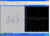
I have this circuit in the simulator but the ocsiloscope still shows some noise in the 12 volt signal.
(with just one pair of TIP104, 105, i still have the same problem)
Is there any better way to do this? Because even with all the amplification I still cant charge it fast enough as to have a straigt edge instead of a curve in the gate voltage.
As the specs says, the standard intel made for the pwm fans used in atx motherboards allows a maximum of 50mA for the pwm signal
(50 sourcing, and 50 sinking (80recomanded) )
So I need to control 24A (8x 3A 12V fans), switching on and of the 12V that goes to the fans.
The pwm signal works at 25Khz, , that's 40µs each cycle, so it has to, at most, charge the gate in less than 0.4µs (for 2% to 98% cycle duty precision)
**broken link removed**
I have this circuit in the simulator but the ocsiloscope still shows some noise in the 12 volt signal.
(with just one pair of TIP104, 105, i still have the same problem)
Is there any better way to do this? Because even with all the amplification I still cant charge it fast enough as to have a straigt edge instead of a curve in the gate voltage.
Last edited: