ljcox said:
[quote="Nigel Goodwin
Transistors commonly go S/C under these conditions, it's crucial to include the diodes to protect the BE junction.
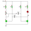
Nigel is right. In the multivibrator circuit shown, it is likely that there will be sufficient energy stored in the capacitors to damage the BE junction.
The transistors would not be damaged with small capacitors, but my understanding is that their gain would be reduced.
Len[/quote]
The circuit showed 10uF, which I would expect to be high enough.
Back in about 1973, at technical college, we were given a project to build (the idea had been kicking about for a long time, but they had never had a class they thought was good enough). It was basically a very simple 'one armed bandit' type device, it used three 7 segment filament displays (back before LED's), using just the three horizontal segments.
Each display had a button underneath it, and pressing the button froze that display - to win you had to stop all three on the same line. A win or lose light lit up accordingly, fed from simple gates.
The project had to be built from only discrete componets, on plain matrix board (using pins), with all components and wiring visible on the top of the board.
The basic design was three astable multi-vibrators feeding three ring of three counters, with bistables used to stop the counters, and diode gates to fed the win/lose lamps.
Because of it's modular nature we were split into teams, each of which built a particular section - mine was the ring of three counters!.
Anyway, the reason for this long story - the team building the astables was run by a guy called Dave, who later became a lecturer at the same college. He didn't fit the diodes, and despite me telling him to, he refused, saying they weren't needed, and simply kept fitting transistors till he found some which managed to survive. From what I remember he had a pile of dead transistors, 30-40 of them!!!.