Continue to Site

Welcome to our site!

Electro Tech is an online community (with over 170,000 members) who enjoy talking about and building electronic circuits, projects and gadgets. To participate you need to register. Registration is free. Click here to register now.

  • Welcome to our site! Electro Tech is an online community (with over 170,000 members) who enjoy talking about and building electronic circuits, projects and gadgets. To participate you need to register. Registration is free. Click here to register now.

Need input: Custom made soldering station!

Status
Not open for further replies.

Jay.slovak

Active Member
Hi guys,

I don't have suitable soldering station and because SMD PCBs are so easy to make with Press-n-Peel I have decided do get new, temperature controlled soldering station. I was looking for one with basic functions (just R/G LED indication and one potentiometer) but all costed $60+ and I am not willing to spend so much!
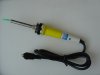
Then I realised I can build my own, for 1/3th of the price, so I bought $15 24V/48W Pro's kit spare soldering iron, with thermojunction temperature sensing.

The thing is I am looking for a way how to correctly feed this thermojunction output to the PICs ADC (16F88 or 18F1320 - to be decided). It's output is at 0.2mV @ room temp and approx. 50mV @ full power (don't know exact temperature). I was thinking of single non-inverting OPamp solution with Gain=50. Is this OK? I am not an expert when it comes to OPamps (eg will Offset voltage be a problem?).

Thanks for all constructive comments! :)
 

Attachments

  • solder_iron.jpg
    solder_iron.jpg
    461 KB · Views: 1,156
  • 2in1_pc_psu.jpg
    2in1_pc_psu.jpg
    129.7 KB · Views: 1,141
  • other_things.jpg
    other_things.jpg
    98.7 KB · Views: 1,146
It dosent need to be realy acurate so an simple op anp shod do it.

Shodnt be to complicated.

Good luck whith it jay.
 
Thanks, but I want it to achive ~5C temperature accuracy.

BTW: The two PSUs are connected in series resulting with 24V/2.2A power output. I placed two 2.2R /20W resistor to the 5V rails as a pre-load.
The PIC runs from +5V rail and is using 2.5V external voltage reference.
 
If you're worried about offset voltage, get an oppamp with offset null option. I've used TLE2142 on most of my projects requiring high precision and low noise.

I don't think that would be an issue anyway. What you really need to do, is perform a 2-point calibration. Pick one temperature at the lower end - let's say 25C, and the second temperature at the higher end, let's say 220C. Run your system and record the voltage your A/D is recording at 25C, run your system again and record the voltage your A/D is recording at 220C. I am assuming your thermistor is has a linear transfer function.
Now you have two points, and once you have two points, you can plot a line, which characterizes your thermistor. In other words, if you make a plot with voltages on your x-axis, and temperatures at your y-axis, you can now convert any voltage into temperature. This is something you'd have to do anyways - to calibrate your system, and it takes care of all the other voltage drops/gains in your acquisition system.
 
Oh and i have a question.Whats cooling the 2nd PC PSU? There is no fan on the other side.Hope you keep it cool enugh.
 
I am planing to do calibration at 0, 25 and 100 C (Because I don't have a thermometer) and I hope it will show me it's temperature/voltage characteristic. What I wanted to know is how to use the OPamp, standart non-inverting or differential?

The PSUs don't make much heat, so the cooling will be sufficient. Originaly they were cooled by 6*6cm FAN @12V, now I am using 8*8 FAN @24V.
 
Hi Jay,

Big problem if you cannot calibrate the highest temperature point. By interpolating 100C to the highest temperature, the error could be large.

Your millivolt temperature signal from the soldering iron tip thermal junction and the 2A PWM current are next to each other in the same cable. Induced noise can be a problem. You have to take into account when designing the solftware.

Maybe you can try the power,measure,power,measure......sequence.
 
Thanks eblc1388 for reply,

I was thinking about the modulation type already, First I wanted to use PWM (and fuzzy logic) but later I decided to use PSM (pulse skipping modulation), so I will measure the temperature between the pulses.

Do you know any commonly available material that I can use to calibrate the iron? (Something that melts @ fixed temperature) I will rise the temperature until it melts so I will know "exact" temperature.
 
I don't know of any substance except different kind of solders that melts at different temperature.

Perhaps you can wait till you are back in University lab where you can have an proper instrument to measure it accurately.
 
Oh well, what can I do. I will try colophony and SnPb solder. I can't wait for University lab, I want to do it ASAP.
 
Using an op-amp is quite easy.You give it the power suply,ground the input - pin,put an resistor betwen the output and the input + and your redy to drive the signla in the input + pin.

You will find evrything on datasheets.

Your planing to boil water whith it and say thats 100 C°
 
Someone Electro said:
Using an op-amp is quite easy.You give it the power suply,ground the input - pin,put an resistor betwen the output and the input + and your redy to drive the signla in the input + pin.

You will find evrything on datasheets.

Your planing to boil water whith it and say thats 100 C°
Berni, I know how to use OPamp! I am just asking if this is a correct way how to do my project, considering I am working with such a low voltage.

Yes I am going to use boiling water, and icy water for calibration.
 
Jay.slovak said:
It's output is at 0.2mV @ room temp and approx. 50mV @ full power
This can't be a simple thermocouple - a 'K' type thermocouple (nickel chromium / nickel aluminium) would give 12.2mV with 300 degrees C difference between hot and cold junctions :?

Is this "thermojunction" a thermopile of some sort (a stack of thermocouples in series) or could it be a resistance thermometer? An RT could have a resistance anywhere from a few hundred ohms upto several k and measure the same regardless of connection polarity, a thermocouple will be only a few ohms and read differently when the meter leads are swapped to reverse its polarity.

If it is a themocouple/thermopile then you will have to measure the cold junction temperature and compensate for it or maintain it a constant temperature -- it's the difference between hot and cold junctions that generates the output. At ambient temperature (hot and cold junctions at same temperature) there will be zero output.

ps. sounds like an ace project - consider a write-up for the 'Projects' forum ?
 
Mechie, maybe I accidentally measured 5mV at 160C, I don't know beacuse I don't have proper equipment. When I was exploring the Iron, I measured ~4ohms and 0.2mV @ room temp, the resistance IS different if I swap the LEADS. Do you have more info regarding thermocouplers? I would love that.

If I finish this project, I might put it into Projects section, but I don't know if others can get those 2 PSUs (taken from very old 386 PC). I used them because I had them and I didn't have suitable transformer (which is also very heavy and expensive).

Thanks for more info.
 
Thermocouple Tables

Thermocouple Tables
NOTE the microvolt values given are for a DIFFERENCE between hot and cold junction temperatures - if the cold junction is at 20 degrees C then the microvolt value measured will give the hot junction temperature ABOVE 20 C - the temperatures need to be added
Code:
  K Type        T Type        J Type
Deg C   uV    Deg C   uV    Deg C   uV
  0      0      0      0      0      0
 10    397     10    391     10    507
 20    798     20    790     20   1019
 30   1203     30   1196     30   1537
 40   1612     40   1612     40   2059
 50   2023     50   2036     50   2585
 60   2436     60   2468     60   3116
 70   2851     70   2909     70   3650
 80   3267     80   3358     80   4187
 90   3682     90   3814     90   4726
100   4096    100   4279    100   5269
110   4509    110   4750    110   5814
120   4920    120   5228    120   6360
130   5328    130   5714    130   6909
140   5735    140   6206    140   7459
150   6138    150   6704    150   8010
160   6540    160   7209    160   8562
170   6941    170   7720    170   9115
180   7340    180   8237    180   9669
190   7739    190   8759    190  10224
200   8138    200   9288    200  10779
210   8539    210   9822    210  11334
220   8940    220  10362    220  11889
230   9343    230  10907    230  12445
240   9747    240  11458    240  13000
250  10153    250  12013    250  13555
260  10561    260  12574    260  14110
270  10971    270  13139    270  14665
280  11382    280  13709    280  15219
290  11795    290  14283    290  15773
300  12209    300  14862    300  16327
310  12624    310  15445    310  16881
320  13040    320  16032    320  17434
330  13457    330  16624    330  17986
340  13874    340  17219    340  18538
350  14293    350  17819    350  19090
360  14713    360  18422    360  19642
370  15133    370  19030    370  20194
380  15554    380  19641    380  20745
390  15975    390  20255    390  21297
400  16397    400  20872    400  21848
410  16820    410           410  22400
420  17243    420           420  22952
430  17667    430           430  23504
440  18091    440           440  24057
450  18516    450           450  24610
460  18941    460           460  25164
470  19366    470           470  25720
480  19792    480           480  26276
490  20218    490           490  26834
500  20644    500           500  27393


Materials used in manufacture and international colour codes (NOTE regional variations may be found)...

K Type is nickel-chromium(+) and nickel-aluminium(-)
positive lead is green
negative lead is white - this wire is MAGNETIC

T Type is copper(+) and copper-nickel(-) (also called copper / constantan)
positive lead is brown
negative lead is white

J Type is iron(+) and copper-nickel(-)
positive lead is black - this wire is MAGNETIC
negative lead is white

There are another half-dozen recognised thermocouples not listed here.
for more info try https://www.tc.co.uk/
:shock:
 
If you can ground one output of the thermocouple, you're best off with using a simple non-inverting configuration (very high input inpedance). If on the other hand, you need to leave the thermocouple floating you should go with a differential amplifier - AD602 usually worked great for me in those cases. If you don't feel like spending a few bucks on the AD602, get 3 regular op-amps (or a quad op-amp in one package), and set it up in the differential configuration (like instrumentation op-amps do)...

Also - looking at the tables, it doesn't look like your material characteristics are linear. which means you'll either have to get more points, and do some serious curve fitting, or use a lookup table. The best approach would probably to combine the two. I.E. use lookup table of values every 10C or so, and then assume linearity between the two points, and interpolate...

Also - why not use an infrared thermometer to make measurements - I'm sure you can get one real cheap on e-bay, and it would also come in handy on other projects, so it's not like you're wasting money? Otherwise you'll have a tough time determining temperature based on a material melting - because that varies depending on pressure.
 
Thank you mechie and eemage21.

Another question, what does "MAGNETIC" mean? And where is located to "cold" end of the thermocouple? Because the thermocouple is integrated in the iron, I don't know which type it is, but I gues I will find out when I will calibrate it in 100C water.

I have decided to use non-inverting auto-zero offset OPamp, that should work (Thermocouple can be tied to ground).

Also - why not use an infrared thermometer to make measurements - I'm sure you can get one real cheap on e-bay, and it would also come in handy on other projects, so it's not like you're wasting money? Otherwise you'll have a tough time determining temperature based on a material melting - because that varies depending on pressure.
Actually that is a good idea!
 
eemage21 said:
... Otherwise you'll have a tough time determining temperature based on a material melting - because that varies depending on pressure.

Melting point varies with pressure? That's new to me. What are we talking here, a few degrees or 0.001 degree with normal pressure changes?
 
Status
Not open for further replies.

Latest threads

New Articles From Microcontroller Tips

Back
Top