Hello.
I programmed my unit so every time I want to switch an appliance with the relay, ON or OFF, the switching will happen at zero-cross of the line voltage.
I want now to check with the oscilloscope that the switching indeed happens at zero-cross.
I connected to the relay a light bulb, and connected the probe's pins to both legs of the light bulb.
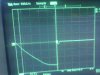
Now, I dont know how do I tell the scope to freeze the picture when the 220Vac turns zero, so I can see at what voltage of the light bulb, it dropped to zero, hopefully it will be a very small voltage thats close to zero.
If it was 220VDC, I would put a the trigger line a little above zero, and would tell the 'scope to freeze the picture when the voltage crosses the trigger line from above downwards.
But how do you it with AC, when it always crosses the trigger line?
I'd appreciate any help on this.
Thank you very much.
I programmed my unit so every time I want to switch an appliance with the relay, ON or OFF, the switching will happen at zero-cross of the line voltage.
I want now to check with the oscilloscope that the switching indeed happens at zero-cross.
I connected to the relay a light bulb, and connected the probe's pins to both legs of the light bulb.
Now, I dont know how do I tell the scope to freeze the picture when the 220Vac turns zero, so I can see at what voltage of the light bulb, it dropped to zero, hopefully it will be a very small voltage thats close to zero.
If it was 220VDC, I would put a the trigger line a little above zero, and would tell the 'scope to freeze the picture when the voltage crosses the trigger line from above downwards.
But how do you it with AC, when it always crosses the trigger line?
I'd appreciate any help on this.
Thank you very much.
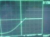
") ), but sometimes i see at the middle of the screen a complete sine wave, i dont see where its cut off.
), but sometimes i see at the middle of the screen a complete sine wave, i dont see where its cut off.