Continue to Site

Welcome to our site!

Electro Tech is an online community (with over 170,000 members) who enjoy talking about and building electronic circuits, projects and gadgets. To participate you need to register. Registration is free. Click here to register now.

  • Welcome to our site! Electro Tech is an online community (with over 170,000 members) who enjoy talking about and building electronic circuits, projects and gadgets. To participate you need to register. Registration is free. Click here to register now.

Need help with what I think is a simple project.

Status
Not open for further replies.

Moron

New Member
Hi everyone.
I'll keep it simple.

I'm a boxer.
I need something that has two lights and, at random intervals between 1-3 seconds apart, flashes either the left or right light. In my case, the application is for fighters to work on their reaction times.

I've found all sorts of widgets on Google that appear to approximate what I'm looking for, but I don't understand their application.

The other problem is that I know nothing about electronics so this would literally have to be something I can put together with conductive 'solder glue' and written for someone who is generally stupid.

It seems easy enough, but I don't know enough to make that call.
Can anyone help?

Thanks
 
The biggest problem is "random", but you could probably do it with a PICAXE. https://www.picaxe.com/

I also get the impression that the left or right is random as well.

You also need to better define what a light is. Are we talking an LED or a 120 VAC light bulb or something else.

So, we basically need some sort of computer that has the ability to generate random numbers and time.
Those computers generally can generate a random number between 0 and 1 and it's easy to make that 1-1000 or whatever. Your 1-3 seconds might mean as short as 0.1 s apart with a minimum of 1 sec and a maximum of 3 seconds.

Dunno, if we are looking at a battery powered device with two LED's or something else.
 
Yeah, battery powered with two LEDs spaced a couple feet apart would work fine.

The basic idea is that I just two random signals, left and right, that signal at random intervals between 1-3 seconds.
Lets say LED lights.

Red light goes off

1.34 seconds later, red again

2.34 seconds later, green light

1.45 seconds later, reg light

2.66 green light

1.03 green light

1.78 green light

2.04 red light


You get the idea. Basically, a light that vacillates back and forth at random intervals.
It would be a tool to train my fighters reaction.
 
So, you could basically do it with the starter Pack, here: https://www.picaxe.com/Hardware/Project-Boards/PICAXE-18-Project-Board/ The starter pack is in the "Related Products".

2 resistors and 2 LEDs complete the basic kit. The resistors would probably be less than (4.5 V-1.2 V-0.6 V)/20E-3mA = ohms. 4.5 is the power source, 1.2 is the LED drop, 0.6 is the drop across the driver

So something around 135 ohms 1/4 Watt resistor will do.

Then the stuff, that they don't tell you about like the power switch, the battery choice (3-AA's) look like they would work., LED mounting and the case.

Then there would have to be an ON time for your LED as well.

Here is a note on random numbers: https://en.wikipedia.org/wiki/Random_number_generation

So, start reading.

Here: https://www.picaxe.com/BASIC-Commands first. Look at random, pause, high and low.

The real issue is dealing with only integers fom 0-65535. One possible way to deal with the problem is to use a logical and. If you and a number with 255 which is a power of 2-1, you get a number between 0 and 255. Another way is by integer dividing. and another by waiting multiple times.

e.g. you said 3 sec, but lets say we were able to count to 1023 mS.
Wait 1000 mS
get a random number
and it with 1023
Wait that number of ms
random
AND with 1023
wait taht number of ms
In the above, we would have waited 0 to 2.048 seconds + 1 second which is close enough.

The pseudocode goes something like:
Initialization
Like set the 2 ports to be an ouput

LOOP:
Get a random number
AND it with 1
Call this variable Port

Wait 1 sec
Get a random number
AND it with 1023
Wait that number of mS

Get a random number
AND it with 1023
Wait that number of mS

If port = 0 then turn port 0 on and turn port 1 off
If port =1 the turn port 1 on and turn port 0 off

Wait 750 mS

Turn both ports off

Go to Loop

If your not happy with the randomness, then add the timer or a Real time clock/calendar which would be a lot harder.
 
Last edited:
Conceptually, I understand very little of this, which suggests I may just need to find a solution based on improvisation of parts and materials I have around me rather than bona-fide electrical engineering a dedicated product.
 
Conceptually, I understand very little of this, which suggests I may just need to find a solution based on improvisation of parts and materials I have around me rather than bona-fide electrical engineering a dedicated product.

It is much easier to do with computer program. You make the monitor black and you randomly paint your lights - green on the left side and right on the right side.
 
You requirements may sound simple, but they aren't. ;) Getting lights to flash at random intervals between 1s and 3s is not a trivial task. That's why a microprocessor is likely the easiest way to do it.
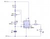
 
Scroll down this page for 'random blinking leds'

http://www.talkingelectronics.com/projects/200TrCcts/101-200TrCcts.html#35

This isnt exactly what you asked but it gets close, there are 7 leds which light up randomly, the only thing is you might get 2 together.
I remember seeing a 'guessing game' circuit in a circuit book, where you applied power and 1 of 2 leds lit up randomly, sounds more like what you want, and it was only 2 transistors and a few resistors.
 
I think this is simpler than some people are making out.

First everyone is saying that we have to have random time and random lights. I have an idea - in software have the code quickly toggle between right and left states with the state only becoming fixed after 'random' time. Thus if you have random time you have random(ish) lights - good enough for the average boxer anyway.

the attached circuit is a hardware version of a digital dice - uses the length of a button press to get a ‘random’ value. we just need to work out a random input and we've got you a solution.
 

Attachments

  • Capture.JPG
    Capture.JPG
    28 KB · Views: 159
This is an example of a 'light to frequency' circuit - it would need modification so the frequency range is correct but after that you could put the LDR near the boxer in question and use his shadow to provide your random interval.

You would need to put 555 output (where the LED is) to the EN input of the counter in the previous circuit. And in the previous circuit you need to connect R (reset) to 3 (so the counter just flips between 1 and 2). Another 555 astable would be needed to provide the clock frequency
 

Attachments

  • Capture2.JPG
    Capture2.JPG
    19.3 KB · Views: 170
I think this is simpler than some people are making out.

First everyone is saying that we have to have random time and random lights. I have an idea - in software have the code quickly toggle between right and left states with the state only becoming fixed after 'random' time. Thus if you have random time you have random(ish) lights - good enough for the average boxer anyway.

the attached circuit is a hardware version of a digital dice - uses the length of a button press to get a ‘random’ value. we just need to work out a random input and we've got you a solution.
You can make the requirements simpler to simplify the problem but that's not what he asked. He wants random times between 1 and 3 seconds. That is not readily done with a simple circuit.
 
Very true crutschow, but considering this guy by self confession doesn't know what he's doing I think we can suggest 'better' or more realistic requirements.

I'm sure that for boxing training its not necessary to have a truly random number sequence generator, even a long pre-generated pattern might be sufficient if it's long enough for an hour or so of training.

I think we have an overcomplicated problem due to misunderstood requirements ....
 
How long do you want each LED to flash? Do you want a short flash or a long flash?
 
Sorry for the late reply.
Obviously I'm not a regular member and just check back in whenever it jumps to my mind.

How long do you want each LED to flash? Do you want a short flash or a long flash?

Don't care as long as its clear. It can stay on, it can blink for whatever fraction of a section.

Also don't care if it's a scientifically impeccable random sequence. I just need a little blinking light that goes between left and right at relatively unpredictable ways in relatively unpredictable times. Does it have to be perfectly 1-3 seconds? No. All I'm trying to accomplish is the outcome of a little 'signal' that will train boxers response times.

Shocking that it is this complicated from a hardware perspective. I guess if I can't build something electro-mechanical in nature, I'll just improvise that functionality out of stuff that already exists or maybe write an iPhone app that does it and just put it in front of them.
 
I think you can do this with VBA and a couple of audio files, and a pair of circuits to turn on a light when the sound plays. The audio files would be a tone for the left channel, and a tone for the right channel (also have the advantage they could be played through speakers if this helps at all). With a little added complexity you could have two tones per channel, so you could have four LED's if you wanted to have two kinds of reaction for example blocking as well as punching.

So you fire up your favourite MS Office application, open the file that has the VBA, plug your sound-to-light devices in to the computer's speaker output and off you go.

VBA has a tolerable random number generator, the program would run in a loop so it just plays the tones infinitely. There's tons of help on the 'net with writing the programs, and the help files are mostly helpful if you apply a little thought.

You could also do it with VBScript, though it's a little harder to write, or whatever scripting language you like, or like you say, write an app for that.

Only problem is you would need to have a computer of some description in the room, although it could be sited well out of the way with just the light boxes near the training area.
 
Something based on this perhaps (though it's a tad ambitious for an electronics beginner)?
BoxingLights.gif
U1a forms a first oscillator which clocks decade counter U2. The counter outputs switch resistors R1-R3 in a pseudo-random sequence. C2 charges via the switched resistor (not necessarily the same one throughout the charge period) and is discharged via D18/R4 under the control of U1b, thus providing a second oscillator. Since the U1a oscillator is anharmonic with respect to the U1b oscillator the pulses from U1b have a random period. R1-R3 and C2 are chosen such that this period is within the range ~ 1sec-3sec. The duration of each pulse is ~ 0.3-0.5 sec, determined by R4C2. Each pulse clocks U3a to latch the current state of U1a, hence providing a random left/right control output from the latch. This is combined with the U1b pulses in diode OR gates D14-D17, R5, R6 to switch on LED1 or LED2 for the pulse duration.
A potentiometer SetBias is included to adjust the mark/space ratio of the U1a oscillator so that the probability of left/right can be weighted in favour of one particular side. This allows a boxer to concentrate more on left or right punches as necessary.
 

Attachments

  • BoxingLights.asc
    7.3 KB · Views: 160
Last edited:
Something based on this perhaps (though it's a tad ambitious for an electronics beginner)?
View attachment 75695
U1a forms a first oscillator which clocks decade counter U2. The counter outputs switch resistors R1-R3 in a pseudo-random sequence. C2 charges via the switched resistor (not necessarily the same one throughout the charge period) and is discharged via D18/R4 under the control of U1b, thus providing a second oscillator. Since the U1a oscillator is aperiodic with respect to the U1b oscillator the pulses from U1b have a random period. R1-R3 and C2 are chosen such that this period is within the range ~ 1sec-3sec. The duration of each pulse is ~ 0.3-0.5 sec, determined by R4C2. Each pulse clocks U3a to latch the current state of U1a, hence providing a random left/right control output from the latch. This is combined with the U1b pulses in diode OR gates D14-D17, R5, R6 to switch on LED1 or LED2 for the pulse duration.
A potentiometer SetBias is included to adjust the mark/space ratio of the U1a oscillator so that the probability of left/right can be weighted in favour of one particular side. This allows a boxer to concentrate more on left or right punches as necessary.

In spite of the fact that you may as well have written that in Russian and I'd stand an equal chance of fully comprehending it, based on what little I know, that seems to be essentially bang on, with the positively brilliant addition of a bias pot to weight the blinking to left or right (a critical factor in fight training, since you may be fighting a southpaw)

I don't know how patents and intellectual property work in the electrical engineering game but if that does what I think it does, with the right 'external packaging', that could become standard kit in boxing/combat sports gyms.

You might want to patent that. You could probably get an existing sports gear manufacturer to tool up a production run, keep it equally cheap and simple, it would sell like a motherfucker and you'd get royalties.

If it does, please remember the poor moron on the internet who initiated the discussion and perhaps send him a free unit.
 
Last edited:
Hi Mr On,

I understand you might be a bit frustrated of what should be something simple gets to be so complex in this forum. When skimming through the posts I've imagined your rolling eyes.

Well for starters you can offer them guys over here to help build one and sell it to you for a reasonable price. Quote your price. Somebody might take it up. It is pretty simple for a final year engineering student to do (Well it is for me). I can build one but with whatever the time I have is quite limited.

Keep in mind the guys over here have taken quite a lot of "customer feedback" for a free forum. So.... what I'm trying to say is: just hang in here and bear with us geeks.

Cheers.
 
I don't know how patents and intellectual property work
I do. Used to be my day job!
You might want to patent that
Now that I've published it I can't do that :). I offer it free to the world and his wife. The publication also means that no one else can patent it, so wouldn't be able to charge exorbitant prices in a monopoly market.
Sorry about the Russian, but the explanation of the circuit might be of some use to other forum members. Glad you like the bias bonus.
 
Status
Not open for further replies.

Latest threads

New Articles From Microcontroller Tips

Back
Top