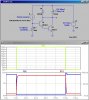
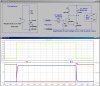
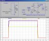
Hi. I am trying to figure out how to get a relay or if necessary a series of relays to trigger from a LED that has a voltage of 2V and power a household 120V AC. The plan is to get a horn or alarm to trigger when the LED lights. The LED is soldered onto the circuit board so the new circuit would have to be connected in parallel with it.
Thanks for any help.
Thanks for any help.
")
