...
But, I've always wondered about ground plane. Your diagram has 2 separate grounds.
Is there a difference in the 2 grounds Appliance vs Wall wart or Are they just both at 0vdc and not to worry ?
Actually, LTSpice lets you connect two nodes "by name" without having an explicit wire drawn. So there actually is only one global ground (which Spice requires), but it just happened to be called "Cathode"
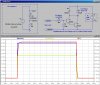
Actually, I was trying to show that the relay circuit is not grounded until the bottom clip lead (Cathode) is attached to the appliance. Suppose that for some reason, the Cathode of the LED was not connected to "ground", but say the series resistor and the LED were reversed inside the appliance. By having the relay circuit "float", it would still work... Note the current through the relay coil, which is all that matters...
Attachments
Last edited:
")
