Continue to Site

Welcome to our site!

Electro Tech is an online community (with over 170,000 members) who enjoy talking about and building electronic circuits, projects and gadgets. To participate you need to register. Registration is free. Click here to register now.

  • Welcome to our site! Electro Tech is an online community (with over 170,000 members) who enjoy talking about and building electronic circuits, projects and gadgets. To participate you need to register. Registration is free. Click here to register now.

need help with MOC3022 and BT137

Status
Not open for further replies.

aruna1

Member
hello I'm making a remote dimmer and I'm having some trouble with the dimmer circuit. (opto isolator used is MOC3022 and triac used is BT137)

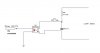
i use following circuit as the dimmer.but after supplying power bulb begins to flicker
**broken link removed**

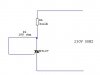
but if i bypass opto-isolator triac turns on continuously
**broken link removed**
. can some one point me what is the error?

i have attached a video too
 

Attachments

  • dimmer.JPG
    dimmer.JPG
    14.1 KB · Views: 1,224
  • dimmer 2.JPG
    dimmer 2.JPG
    6.7 KB · Views: 991
  • MOV00025.zip
    317.6 KB · Views: 728
I deleated my response after viewing your movie. This doesn't look like a workable control circuit. The control has to be synchronized with the cycles of the mains in order for a triac to work. Otherwise, you can only control "on" and "off" I don't know why your light flickers as it does. I'm not familiar with your opto, but I suspect there are others on here who has knowledge of it.
 
I deleated my response after viewing your movie. This doesn't look like a workable control circuit. The control has to be synchronized with the cycles of the mains in order for a triac to work. Otherwise, you can only control "on" and "off" I don't know why your light flickers as it does. I'm not familiar with your opto, but I suspect there are others on here who has knowledge of it.

but this is the circuit given in moc3020-3023 data sheet (only difference is in data sheet circuit has 240v 60hz)
 
edit: I just realise after I posted and deleted it. The MOC is a traic output.

Is U1 LED is connected wrong and leakage current is slightly turning it on?
 
Last edited:
output is connected correct way

Is the LED conencted right way round? ( I have to ask)

I can't see anything wrong with your 'trial' circuit, despite what others say about needing zero-crossing control.

If you're going dim though, maybe you do need some voltage detector circuit.
 
Last edited:
Status
Not open for further replies.

Latest threads

New Articles From Microcontroller Tips

Back
Top