Continue to Site

Welcome to our site!

Electro Tech is an online community (with over 170,000 members) who enjoy talking about and building electronic circuits, projects and gadgets. To participate you need to register. Registration is free. Click here to register now.

  • Welcome to our site! Electro Tech is an online community (with over 170,000 members) who enjoy talking about and building electronic circuits, projects and gadgets. To participate you need to register. Registration is free. Click here to register now.

Need help with Junebug and PIC16F877A

Status
Not open for further replies.

Shipton

New Member
Hey everyone,

So I'm working on a project for university. Because my university graciously does ver ylittle practical, not surprising, I'm stuck because I'm a near-on total newbie to this kind of stuff.

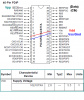
I'm trying to program a PIC16F877A. I have one of those, and a Junebug. I'm trying to figure out howto hook the sucker up to the Junebug, but I have to say I have no idea. The instructions that came with the Junebug are just as cryptic.

First off, the PIC16F877A is indeed a 3.3v uC right?

The diagram in the instructions shows a BUNCH of things that are confusing me. For one, because it's hooked into the ICD, is that good for programming or does that only do debugging?

Next, it shows a bunch of white arrows going to "3.3V," including a lead coming in directly off the 5V pin which puts out a constant ~5V. That makes even less sense to me. What exactly is that trying to say?

Finally, what are the positions of the DIP switches on the board itself?

Any ideas what I could use as a test program when I DO get this sucker running?

Thanks everyone.
 
the device is 5V working, please see the relevant data sheet.
you can program it by connecting the Vpp, Vdd, Gnd, Data and Clock pins as indicated in the PICKIT2 user guide.
A small bit of info is appended here.

The DIP switches are meant for managing the 18F1320, thus all of them can be OFF


you can write a small program like hello world if an LCD module like 2*16 is used.
Even simply, have one or 2 LEDs with current limiting resistors in series, tied from Vdd to two of the port pins-- you could write a program for blinking them alternately or one for shorter period and another for double the time of the first-- just to suggest..

you may place the 16F877A on the bread board, connect the concerned few(5) wires to the relevant pins by short lengths of wires of the extension cable from the programming connector
 

Attachments

  • 16F877A programming  related info.PNG
    16F877A programming related info.PNG
    45 KB · Views: 5,414
Last edited:
If I may ask another question, I'm currently trying to use the program here:
https://www.electro-tech-online.com/threads/help-with-junebug.93870/

To test out the PIC18. However, I get some odd errors, namely MPlab keeps giving me:
Programming Target (25/11/2009 11:12:51 AM)
PIC18F1320 found (Rev 0x7)
Erasing Target
Programming Configuration Memory
Verifying Configuration Memory
PK2Error0027: Failed verify (Address = 0x300001 - Expected Value 0xCF - Value Read 0x7)
PICkit 2 Ready

and

Verifying Target
PKWarn0003: Unexpected device ID: Please verify that a PIC18F1320 is correctly installed in the application. (Expected ID = 0x7C0, ID Read = 0x0)
PK2Error0048: VDD Voltage error. Check target and retry operation.
PICkit 2 Ready

When I first start up the junebug and boot up MPLab and PicKit2, everything is fine. It detects the right device (PIC18F1320), and verifies. But when I try to program it (I import the hex and program), it starts giving me these.
 
Scratch that last reply, got it.

Are there any good tutorials or anything for the JuneBug online?

Also, this uC is going to be the brain of a line following robot. So I have the senors ready. Basically it's on a white surface with a black line. The sensors go HI if they detect black, and output is to a motor controller (L293D) pushing two high-torque DC motors. Just a question because I don't understand the whole dynamics of all this. The PIC16 is online programmable right? So I don't have to remove it from the robot to program it? How does that work?
 
Last edited:
I hooked up the PIC16 as in your diagram which was fairly straight forward

VPP-VPP
5V->VDD (both)
GND->VSS (both)
PGD->data
PGC->clock

I opened up PIcKit2, selected a PIC16F877A as my device, and it reads it. I clicked Verify, and it did verify, but told me there was a VDD voltage level error. "Check target and retry operation." But then when I click verify again, it does it, successfully, but stills gives me that error message/ What does that mean?

I seem to keep having trouble with PicKit acting screwy. Not toally sure why. For isntance right now I have it going to the PIC16 which is empty, and I'm not doing anything, but the clock light is going. And if I read the PIC16, it comes up empty, which is right. But if I do a blank check, it claims it fails at 0x0.

And in MPLab, I get this gem:
Initializing PICkit 2 version 0.0.3.63
Found PICkit 2 - Operating System Version 2.32.0
PICkit 2 Unit ID = OlHoss
Target power not detected - Powering from PICkit 2 ( 5.00V)
PK2Error0024: PICkit 2 was unable to establish a valid Vdd on the target (Attempted 5.00V - Read 2.16V)
PICkit 2 Ready

(PicKit indicates Vdd is stable at 5V)

On second though I'll post this in microcontrollers ~~~ thanks for your helP!
 
Last edited:
Tr to post the schematic of your hardware, if you wanted to try programming the device right from where it is in your board. In case you have used the ICSP data and ICSP clock pins for any purpose in your board, you may have to isolate those loads for a while.
Also the Mclr pin should have a 10K resistor to Vdd and not a direct connection.
Finally Any high value electrolytic capacitor on the VDD pins like 100uF etc would delay development of Vdd unless they are charged, this would raise the error Vdd voltage level alarm.

You may use PIKIT2 ver2.61 or so directly instead of working from MPAB
the hex file location can be given to this software for loading it.
Please note that the VDD derived from the Junebug may not always be able to take load of the target circuitry, depending on the complexity or load. As such you may externally power your board, and in PICKIT2 disable powering from internal.
At this stage please erase and have a check for blank chip before any other step.
let us see whether you can proceed ahead. All the best.
 
Last edited:
Status
Not open for further replies.

Latest threads

New Articles From Microcontroller Tips

Back
Top