Continue to Site

Welcome to our site!

Electro Tech is an online community (with over 170,000 members) who enjoy talking about and building electronic circuits, projects and gadgets. To participate you need to register. Registration is free. Click here to register now.

  • Welcome to our site! Electro Tech is an online community (with over 170,000 members) who enjoy talking about and building electronic circuits, projects and gadgets. To participate you need to register. Registration is free. Click here to register now.

Need help with gm328 components tester

Status
Not open for further replies.

Roman81

New Member
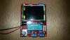
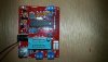
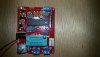
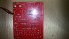
Hi all I'm pretty new to electronics started learning bit by bit a few years ago (mostly from youtube) so my knowledge is very limited. Bought the tester on Aliexpress but didn't notice it was the kit and not assembled 1, in the pics it was all assembled with the case and I didn't read the small print well enough but that's on me. Got it a few days ago and today finally got to assembling it. All went well it turned on no prob but when I tried to calibrate it it did resistance ok but when it came to capacitance testing it showed 6 - 6 - 44 as reference test and after it showed all the capacitores wrong showing way less. Here is a vid of me trying to calibrate
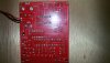
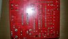
and a few pics showing the assembled module, would love to hear any criticism or suggestions. Please help.
 

Attachments

  • 20190715_213719.jpg
    20190715_213719.jpg
    441.3 KB · Views: 109
  • 20190715_213746.jpg
    20190715_213746.jpg
    502.2 KB · Views: 99
  • 20190715_213750.jpg
    20190715_213750.jpg
    509.5 KB · Views: 122
  • 20190715_213816.jpg
    20190715_213816.jpg
    433.5 KB · Views: 114
  • 20190715_213820.jpg
    20190715_213820.jpg
    389.2 KB · Views: 115
  • 20190715_213835.jpg
    20190715_213835.jpg
    382.4 KB · Views: 115
Can some1 at least point me in the right direction? Here is the schematic of the chip connection.
 

Attachments

  • TransistorTesterVC1.png
    TransistorTesterVC1.png
    35.3 KB · Views: 144
If you google you can find the original design details for these component testers, which includes a description of how all the different modes work, that should help you.

I've built a number of similar units, although I'm not sure I've built that exact one? - and all have worked perfectly.

It looks pretty well put together in the pictures, by following the description of how it works you should be able to find which components you need to make sure are the right values, modern 1% resistors are notoriously difficult to read (I tend to use one of my component testers to double check before I fit them).
 
I did find the oficial German forum ( https://www.mikrocontroller.net/articles/AVR_Transistortester ) and the schematic pic is from there, the author went very briefly over capacitor measurement didn't help much. I can't read electronic schematics well enough to figure out if it uses reference capacitors in the first place never mind which ones are they. If you can point me in the right direction i can check and replace if needed. Someone suggested this vid
but I already watched it and many others befor I asked for help here.
This vid shows at 38:00 him calibrating the unit and his reference capacitors show 42 79 45pf. My unit is showing 6 6 44pf so the last 1 is good but the first 2 show wrong, much lower.
 
Thank you that helped with understanding a little more how it all works, so no ref caps. Measured the 470k resistors and the middle 1 shows 445k in circuit and 469.6 out.
Is the volt ref here is 5V? It showed 5.002V on the LT1004 pins. When i try to measure voltage with the board it shows around 200mV higher than it is.
It doesn't see any resistors that i try to test.
It shows transistor info.
 
Last edited:
I have the same one, I did a calibration for 0 ohms, and didnt bother with cap calibration as when I checked it, it was pretty close without.
 
Status
Not open for further replies.

Latest threads

New Articles From Microcontroller Tips

Back
Top