Continue to Site

Welcome to our site!

Electro Tech is an online community (with over 170,000 members) who enjoy talking about and building electronic circuits, projects and gadgets. To participate you need to register. Registration is free. Click here to register now.

  • Welcome to our site! Electro Tech is an online community (with over 170,000 members) who enjoy talking about and building electronic circuits, projects and gadgets. To participate you need to register. Registration is free. Click here to register now.

Need help with glow plug driver

Status
Not open for further replies.

01sporty

New Member
Hi,

New member here. I'm working on putting together the glow plug driver that I found here: **broken link removed**

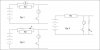
I'm hoping to replace the amp meter that's shown in parallel with the power resistor RM with just a led to let me know that power is going to the plug.

I was told that I could simply replace the amp meter with a led in series with a 470 ohm resistor. This doesn't work so I was hoping someone could tell me the correct way to do this.

Thanks,
Walt
 

Attachments

  • glow3.gif
    glow3.gif
    9.5 KB · Views: 4,002
Please provide the voltage of the battery, and approx glow plug voltage and current they need to work.

It migh tbe possible with just a LED and a change fo resistor values, or you might need something a little more complex like a transistor and a few resistors etc.
 
RC flight boxes are almost always driven from 12V SLA batteries, or directly from a cars alternator, so figure 13.8 volts. I'm not sure of the effect DC resistance of a glow plug, because well it glows so it needs to be measured at temperature. The cold resistance of the plug is going to be dramatically different than the running.
 
... just something to try... don't know if it will work

Try putting an inductance in series with Rm.

... Not absolutely sure about the precise inductance value.
You might try wrapping a length of your connecting wire in a spiral/helix around an iron nail.


Next, put the led, in series with the 470 Ω resistor, as a parallel branch to the Rm+inductor branch.


The resulting led output should be at least a 'blink' .... If this is not satisfactory, then try different numbers of wire turns on the nail inductor.

The principle here is that a transient current through the nail inductor and Rm branch should produce a voltage pulse that is sufficient to light the led, at least momentarily, until the voltage across the inductor dies out.
 
Hi,

The battery is indeed 12 volts. A glow plug is just a platinum winding that acts like a light bulb. They typically run at 1.5 volts and 3 amps but I'm not convinced all that has any bearing on my problem.

I attached a jpeg showing what I believe is the same circuit greatly simplified. Please correct me if I've got it totally bollixed.

Fig. 1 shows the circuit with the amp meter in place. I don't understand this. I was under the impression that amp meters needed to be in series with the load. The RM resistor in parallel just seems to provide a path for those slippery electrons to do an end run around the meter.

Fig. 2 shows the circuit with the resistor/led in place of the meter. This looks even less likely to me and, indeed when I try it, I get nothing out of the led. sigh.

Fig. 3 is what I think is the way it should be wired. It works when I put it together in the simplified form so I cut a new board and I'm soldering it up. Hopefully it will work when I get all that other confusing stuff in place.

Please stop me before I get too far along if you see a problem with my plan. :p

Cheers,
Walt
 

Attachments

  • Led.JPG
    Led.JPG
    16.3 KB · Views: 654
Figure 2 looks good.......

Rm is just a shunt for the meter to read current....

What you need is a resistor that can handle the current of the glo plug and develops sufficient voltage to light an led with a series resistor....

The value of Rm being what it is, is probably too low .. whats the forward voltage of an led? A 5mm red one is typically 2.5volts...so Rm needs to be around a value to generate enough voltage to light the led with its series current limiting resistor
 
Last edited:
My red lEDs are 1.8V. So for a current of 3A I would use an RM resistance of 1.8V/3A= 0.6 ohms. No wonder the device did not work with 470 ohms that is almost 1000 times too high.

You don't know what is the actual current of a glow plug (it is much higher when cool) and you don't know the actual voltage of the LED so the LED will probably burn out without having a resistor in series with it.

Of course the meter and its shunt resistor RM are in series with the load.
 
That first circuit is pretty sophisticated. The 555 power is taken after the glowplug so it requires a working glowplug and good connection before it operates. Then the 555 pulses the FET on which puts around 12v on the glow plug for a short pulse to heat it, and Q2 acts as a crude voltage regulator that waits for the 555 power to be > a voltage before it can fire the 555 again to pulse the glow plug again.

The ammeter looks like an important part of the circuit because you need to see the amps to set the pot to the correct current.

Do you need to set different currents through the glow plug or would you be happy with a simpler circuit that just always runs the glow plug at 3 amps and has a LED to show it is working?
 
A glow plug in a model engine is designed for 1.5V, not 3A.
50 years ago I used a #6 dry cell.
 
That first circuit is pretty sophisticated. The 555 power is taken after the glowplug so it requires a working glowplug and good connection before it operates.

Correct. No switch required. Connect the glow plug and the circuit comes alive. That's the reason for the led, to make sure the plug is good without resorting to peeking into the cylinder.

Then the 555 pulses the FET on which puts around 12v on the glow plug for a short pulse to heat it, and Q2 acts as a crude voltage regulator that waits for the 555 power to be > a voltage before it can fire the 555 again to pulse the glow plug again.

Yes. That's the feature that convinced me to try to build this driver. Once it's tuned in it should provide a good glow until the battery is really drained.

The ammeter looks like an important part of the circuit because you need to see the amps to set the pot to the correct current.

Ordinarily yes, but in my application I'll only be lighting one type of plug. The current is just a rough measure anyway. Usually you set the driver to a level that 'looks good'. After you've melted a couple of expensive plugs, you get a quick feel for how hot is too hot.

Eventually, the pot will be replaced with a resistor.

Do you need to set different currents through the glow plug or would you be happy with a simpler circuit that just always runs the glow plug at 3 amps and has a LED to show it is working?

I would love a simpler circuit if it has the voltage compensation feature but then some of that 'simple' would disappear. Right now I'd just be happy to get this circuit to work. :mad:

More on that later.
 
Figure 2 looks good.......

Rm is just a shunt for the meter to read current....

OK, I don't understand your explanation any more than I understand what is happening with Rm and the meter. According to Wiki: "In electronics, a shunt is a device which allows electric current to pass around another point in the circuit." This is the way I think of a shunt and is just another way to say "The RM resistor in parallel just seems to provide a path for those slippery electrons to do an end run around the meter." :p (pretty bad when I start quoting myself)

The question is kind of moot as it pertains to the led since I think Fig. 3 is going to work without having to work out new values for Rm and the led resistor.
BUT, I would like to try to understand what is happening with the meter and Rm even if I don't intend to use the meter. I'd like to try to understand the entire circuit but I find myself chasing my tail a lot because a lot of this circuit seems to go in circles. sigh.
 
Sporty, the shunt Rm is there for the meter....Without knowing what the meter range is, I'd guess it is not a high current measuring ammeter hence the shunt....

For instance it could be a 0-100 mA ammeter scaled 0-5 amps, therefore for fsd, it needs 100mA, if the max load draw is say 5 amps then 4.9 amps needs to be shunted through Rm....
 
The 0.2 Ω/ 10 watt resistor, RM, would have been used with a specific ammeter, in order to obtain an extended range. ... Possibly, a meter with a 1 mA full scale movement would have been intended for use.

The link here might be useful:
 
You can find easier circuits, assuming 3 Amp for the plug. I´ll have to search info about that.
I could also use such a circuit, as i also have a RC car, a bike and a plane.

You can use a Current Regulator and just vary the value of the program resistor and calculate the output
current from the LM317 / LM338 / LM350 family of three terminal adjustable regulators.
This Current Regulator will work for adjustable regulators with a reference voltage (VREF) of 1.25. LM317 is limited to 1,5Amp.

**broken link removed**

LM350 and LM338 work the same way and support heavier loads.
Its just a matter of downloading the data sheet of the devices and choose one.
The LM350 datasheet includes one 3A constant current circuit with just a 0,4 Ohm, 2 Watt resister.
The LM338 datasheet includes one 5A constant current circuit with just a 0,24 Ohm, 2 Watt resister.

Maybe just using a 2, 3 or 4 position switch for the several kinds of glow plug.
 
Last edited:
Sporty, the shunt Rm is there for the meter....Without knowing what the meter range is, I'd guess it is not a high current measuring ammeter hence the shunt....

For instance it could be a 0-100 mA ammeter scaled 0-5 amps, therefore for fsd, it needs 100mA, if the max load draw is say 5 amps then 4.9 amps needs to be shunted through Rm....

Ok, that makes perfect sense even for me. :D
Sounds like, for my use, I can just toss it. One less thing to go wrong.

In the stock list for the **broken link removed** he just calls for a 1-6 amp dc meter.

When I first started this, I emailed the author of the upgraded circuit. He led me to believe the Rm was needed and told me to put the led and 470 ohm resistor in parallel with Rm. This could have been a language problem since English is not his first language. I tried to get clarification but he never emailed back. Since my first email was unsolicited, I thought best leave it.
 
You can find easier circuits, assuming 3 Amp for the plug. I´ll have to search info about that.

///MAJOR SNIPPAGE///

Maybe just using a 2, 3 or 4 position switch for the several kinds of glow plug.

Most of the glow drivers I've seen have all used the 555 timer. Others seem to have huge heat losses.

It does seem to me that this circuit should be able to be simplified by someone that is familiar with lm555 circuits. Most of the general monostable/pwm circuits I've seen, are a lot less complex than this one.
 
Why use a switch to change the current?
Aren't all glow plugs for model engines 1.5V? My glow plugs also worked fine when my 1.5V battery dropped to 1.2V. When the battery was only 1.0V when loaded then the engines were difficult to start.
 
RC flight boxes are almost always driven from 12V SLA batteries, or directly from a cars alternator, so figure 13.8 volts. I'm not sure of the effect DC resistance of a glow plug, because well it glows so it needs to be measured at temperature. The cold resistance of the plug is going to be dramatically different than the running.

Glow plugs ar usually around 2 volts.

I just used a simple drop down regulator with the transistor on a medium sized heatsink. This can be used from a car battery.
I put a pot on the voltage control to adjust the glow plug brightness. Some can be as low as 1.5 volts.
 
Last edited:
your battery is 12.6V or more.
the glow plug needs only 1.5V.
Then you are wasting 11.1V at 3A (33.3W) making heat. Then the circuit uses 7.4 times the power of the glow plug. What a waste of power!

You should use a switched-mode buck power supply to efficiently convert 12.6V to 1.5V at 3A.
 
Status
Not open for further replies.

Latest threads

New Articles From Microcontroller Tips

Back
Top